-
Jan 04,2020
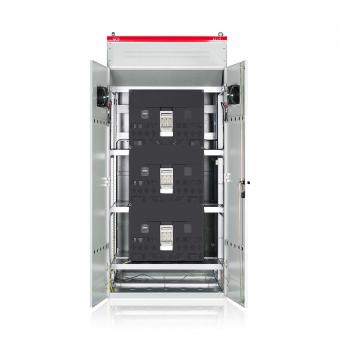
SVG Principle The principle of the SVG is, when the load is generating inductive or capacitive current, it makes load current lagging or leading the voltage. SVG detects the phase angle difference and generates leading or lagging current into the grid, making the phase angle of current almost the same as that of voltage on the transformer side, which means fundamental power factor is unit. Compare...
read more
-
Jan 03,2020
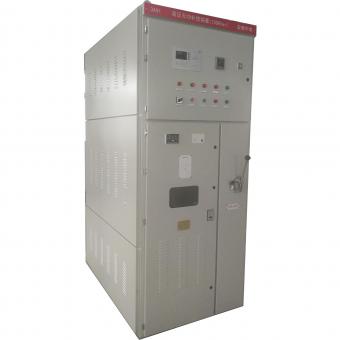
Compared with SVC, SVG is superior to SVC in the following aspects: SVG: Static Var Generator(also as know static synchronous compensator or Statcom) SVC: Static Var Compensator 1. Advanced working principle (1)Static Var Compensator can be seen as a dynamic source of reactive power. According to the requirements of accessing the grid, it can provide capacitive reactive power to networks, and...
read more
-
Jan 02,2020
The effects of harmonics on loads The following two types of effects appear in the main equipment: immediate or short-term effects and long-term effects. Immediate or short-term effects: Unwanted tripping of protection devices, Induced interference from LV current systems (remote control, telecommunications), Abnormal vibrations and noise, Damage due to capacitor thermal overload, Faulty operation...
read more
-
Dec 25,2019
We make a simple introduction about harmoincs in networks,welcome to communicate with us about harmonics and how to solve. General Introduction Harmonics are usually defined by two main characteristics: Their amplitude: value of the harmonic voltage or current. Their order: value of their frequency with respect to the fundamental frequency (50 Hz). Under such conditions, the frequency of a 5th ord...
read more
-
Dec 28,2019
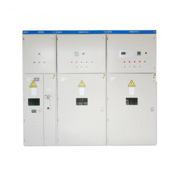
Reactive power is necessary to generate magnetic fields, e.g. in motors, transformers and generators. This power oscillates between the source and the load and represents an additional loading. Static var Compensator (SVC) and static var generator can suppress the voltage fluctuation, flicker and rapidly compensate the reactive power and the quality of electric power can be improved. If you have q...
read more
-
Dec 19,2019
Method for determining compensation (Power Factor correction Guidelines) Step 3: Allowance for operating conditions and harmonics Capacitor banks should be selected depending on the working conditions expected during their lifetime. Allowing for operating conditions The operating conditions have a great influence on the life expectancy of capacitors. The following parameters should be taken into a...
read more
-
Dec 19,2019
Method for determining compensation (Power Factor correction Guidelines) Step 2 Selection of the compensation type Different types of compensation should be adopted depending on the performance requirements and complexity of control: Fixed, by connection of a fixed-value capacitor bank Automatic, by connection of a different number of steps, allowing adjustment of the reactive energy to the requir...
read more
-
Dec 19,2019
Method for determining compensation (Power Factor correction Guidelines) Step 1 Selection of the compensation mode The location of L.V capacitors banks in an installation constitutes the mode of reactive power compensation, which may be central (one location for the entire installation), by sector or group (section-by-section), at load level, or some combination of the latter two. In principle, th...
read more
-
Dec 18,2019
Single busbar compensation Overview An installation with a single LV busbar is that most often encountered. This type of installation requires that the reactive power can change with respect to the methods defined previously. Compensation uses all the receiving devices of the installation and the amperage of the current transformer is determined according to the total current conducted through the...
read more