The Dangers of Over-compensation in Capacitor Cabinets
Aug 06,2026
In power distribution systems, capacitor banks compensate for the reactive power generated by inductive loads using parallel-connected low-voltage power capacitors; this improves the power factor, reduces line losses, and avoids utility company penalties. However, a common misconception exists: the belief that the more capacitors are engaged—and the higher the resulting power factor—the better. In reality, the opposite is true. When compensation capacity exceeds the system's actual reactive power demand, "over-compensation" occurs; far from being beneficial, this triggers a chain reaction of harmful consequences.
Simply put, over-compensation means the capacitors have "overdone" the job, feeding capacitive reactive power back into the grid. Let us now break down the four primary hazards associated with this abnormal operating condition.
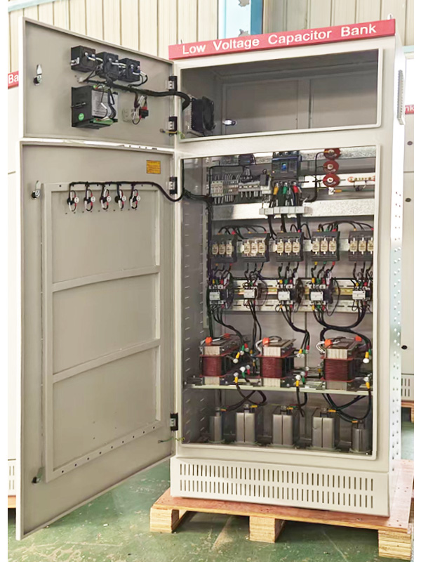
1.The Dangers of Over-compensation in Capacitor Cabinets
-
When capacitors inject excessive capacitive reactive power into the grid, the busbar voltage tends to rise continuously; this phenomenon of "capacitive voltage rise" resulting from over-compensation is quite common. In practice, it is frequently observed that system voltage climbs to 430V or even 440V after compensation capacitors are switched on. When the system voltage exceeds the rated voltage of the electrical equipment, sensitive devices—such as variable frequency drives (VFDs), PLCs, precision power supplies, and lighting fixtures—are subjected to prolonged over-voltage operation. This not only accelerates the aging of equipment insulation and shortens service life but can, in severe cases, lead to the equipment burning out completely.
-
In the event of over-compensation, the system's power factor drops significantly—specifically, the system shifts from an inductive lagging state to a capacitive leading state, with the power factor registering as negative or indicating a leading condition. When a capacitor compensation cabinet causes over-compensation, the proportion of reactive power in the grid increases while the proportion of active power decreases, resulting in a marked decline in the power factor.
-
Long-term overloading of equipment within the capacitor cabinet accelerates capacitor aging and can even lead to explosions. Over-compensation imposes an excessive load on the cabinet—exceeding its rated capacity—causing issues such as overheating and short circuits that compromise stable operation. Continuous operation under over-voltage or over-current conditions accelerates insulation degradation; in severe cases, this can result in insulation breakdown or even an explosion.
-
The interaction between the capacitive reactance of capacitors at harmonic frequencies and the inductive reactance of the system can lead to parallel or series resonance, thereby significantly amplifying injected harmonics. Consequently, capacitor banks experience excessive harmonic currents and overvoltages, resulting in abnormal heating, degraded partial discharge performance, and accelerated insulation aging; in severe cases, this can trigger multiple fuse blowouts, casing bulging, burnout, or even explosions.
2.How do you troubleshoot and resolve over-compensation issues?
-
For manually switched compensation cabinets: immediately manually disconnect a portion of the capacitor switching devices (contactors or circuit breakers) to reduce the number of capacitors connected to the grid; subsequently, re-evaluate the reactive power demand of the load and devise an appropriate capacitor switching strategy for various load conditions.
-
For automatic switching compensation cabinets: first, check if the controller display is normal and compare the readings with those of the power distribution instruments to verify the accuracy of the sampled signals (CT and voltage); next, inspect the wiring of the capacitor bank circuits to ensure correctness; if the wiring is correct, check for the presence of impulsive loads—since rapid fluctuations in such loads can prevent conventional switching devices from responding in time, the use of thyristor-based switching devices (with a response time of ≤20 ms) is an effective solution for these operating conditions; finally, verify that the target power factor setting is reasonable (typically set to a lagging power factor of 0.95–0.98).
-
In systems utilizing dynamic compensation devices (such as SVG or SVC)—which are capable of continuously and smoothly adjusting reactive power from capacitive to inductive—over-compensation is unlikely to occur; should any abnormality arise, the equipment should be inspected for faults or incorrect parameter settings. Furthermore, in systems subject to harmonic pollution (containing significant non-linear loads such as variable frequency drives, DC motors, and UPS units), reactors should be connected in series within the capacitor circuits (typically with a reactance rate of 6%–7%) to suppress harmonic amplification and mitigate the risk of resonance.
Over-compensation entails a range of risks—spanning from voltage-related damage and equipment failure to financial penalties—demonstrating that "more compensation" is by no means better. Achieving proper and rational reactive power compensation requires not only precise calculations during the electrical design phase but also comprehensive management across the entire lifecycle, from controller selection and switching strategies to routine operation and maintenance.