Low Power Factor Operation of Induction Motor
Induction Motors finds various applications in industries and household equipments. Such machine requires magnetic fields for its functioning hence, it draws magnetizing current from the source. The magnetizing current is the current that establishes the flux in the air gap of an Induction motor and this is independent of the load on the motor. It is typically around 20% to 60% of the full load current of the motor. Magnetizing current does not contribute to the work output of motor, as its role is to provide a medium (magnetic field) required in power exchange between stator and rotor through induction principle. Generally an Induction motors operates at low power factor (approx pf 0.2 to 0.4) during light load or no load condition and at full load (approx pf 0.8 to 0.9). At low load or no load condition because of presence of only magnetizing current in the stator windings, causes low power factor operation of the power system, since magnetizing current is highly inductive in nature.
A low power factor operation results in excess burden on generators (increase KVA demand) and for the same power output at constant voltage value of current increases which leads to increase in conductor size hence increases the cost of transmission lines further due to excessive high current in transmission conductors, increases copper losses which results in poor transmission efficiency and a poor voltage regulation due to large voltage drop hence it is advisable to operate induction motors at full load.
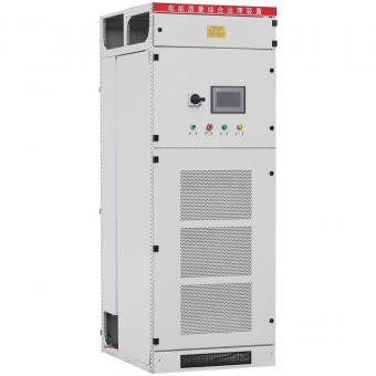
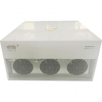
In order to reduce the losses due to low power factor operation of induction motors especially in transformers and distribution equipments, power factor corrections are required like capacitor bank, synchronous phase modifiers etc,their role is to compensate for the reactive power demand of the induction motors and to restore the power factor as close to unity, as it is economically viable.
Power factor correction of induction motors
Because of the small kW consumption, the power factor of a motor is very low at no-load or on light load. The reactive current of the motor remains practically constant at all loads, so that a number of unloaded motors constitute a consumption of reactive power which is generally detrimental to an installation, for reasons explained in preceding sections.
Two good general rules therefore are that unloaded motors should be switched off, and motors should not be oversized (since they will then be lightly loaded).
The bank of capacitors should be connected directly to the terminals of the motor.
It is recommended that special motors (stepping, plugging, inching, reversing motors, etc.) should not be compensated.
After applying compensation to a motor, the current to the motor-capacitor combination will be lower than before, assuming the same motor-driven load conditions. This is because a significant part of the reactive component of the motor current is being supplied from the capacitor, as shown in Figure.

How self-excitation of an induction motor can be avoided
When a motor is driving a high-inertia load, the motor will continue to rotate (unless deliberately braked) after the motor supply has been switched off.
The “magnetic inertia” of the rotor circuit means that an emf will be generated in the stator windings for a short period after switching off, and would normally reduce to zero after 1 or 2 cycles, in the case of an uncompensated motor.
Compensation capacitors however, constitute a 3-phase reactive load for this decaying emf, which causes capacitive currents to flow through the stator windings. These stator currents will produce a rotating magnetic field in the rotor which acts exactly along the same axis and in the same direction as that of the decaying magnetic field.
The rotor flux consequently increases; the stator currents increase; and the voltage at the terminals of the motor increases; sometimes to dangerously-high levels. This phenomenon is known as self-excitation and is one reason why AC generators are not normally operated at leading power factors, i.e. there is a tendency to spontaneously (and uncontrollably) self excite.
Notes:When a capacitor bank is connected to the terminals of an induction motor, it is important to check that the size of the bank is less than that at which self-excitation can occur.
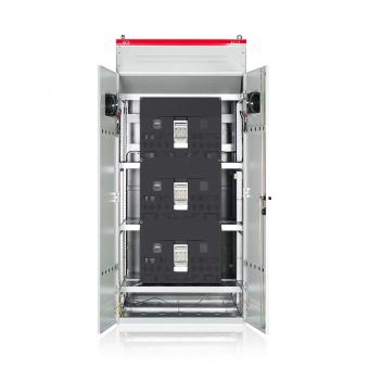
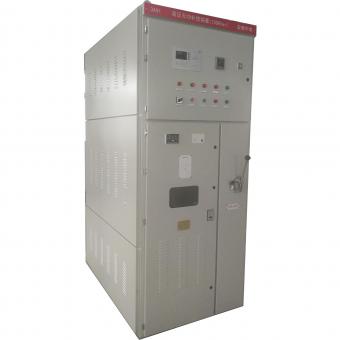
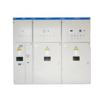
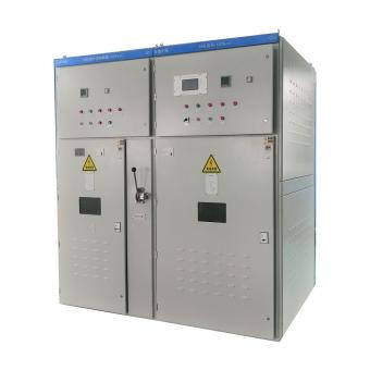
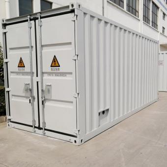
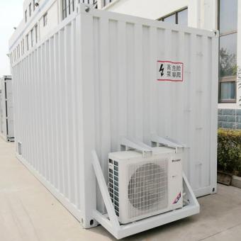
Individual compensation for MV motors.
Following 10kv 400kvar capacitor banks are for 10kv motors


NO.25,JINHE RD,HUAIYUAN ECONOMIC DEVELOPMENT ZONE ,BENGBU,ANHUI
Scan to WhatsApp: