Internal structure and working principle of SVG
Mar 14,2025
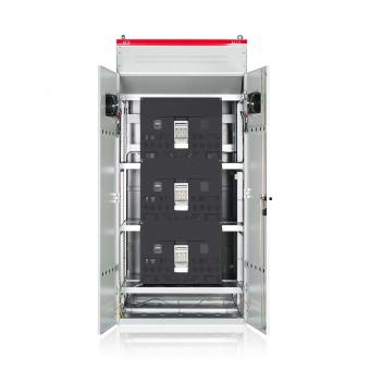
Internal structure
1. Control part: mainly composed of computer, control board, sampling board, drive board, etc. The sampling board collects the voltage, current and other parameters of the power grid in real time. The control chip calculates the reactive power to be compensated based on the sampling data, and then the drive board sends a trigger signal to the power part to control the power part to work.
2. Power part: The core is the power semiconductor bridge converter. The basic circuit structure is a voltage-type bridge inverter circuit, which consists of a DC capacitor and an inverter bridge. The DC capacitor is an energy storage element that provides a stable DC voltage for the bridge converter. The inverter bridge is composed of semiconductor devices that can be turned off, such as IGBT. By controlling the on and off of the IGBT, the DC voltage is inverted into an AC voltage with adjustable frequency and amplitude on the AC side.
3. Starting part: including connecting reactors, starting resistors and bypass switches. The reactor is connected in series between the power part and the power grid to prevent overcurrent, filter ripple and connect two voltage sources. The starting resistor is connected in series in the loop at the moment of starting to prevent the starting current from being too large and burning the DC capacitor and power devices. The bypass switch is connected in parallel with the starting resistor. After the equipment is started, the starting resistor is bypassed through the bypass switch to reduce active power loss.
Working principle
SVG connects the self-commutated bridge circuit to the power grid through the reactor or directly in parallel. By adjusting the phase and amplitude of the output voltage on the AC side of the bridge circuit relative to the system voltage, or directly controlling its AC side current, the circuit absorbs or emits reactive current that meets the requirements to achieve dynamic reactive compensation. The specific process is as follows:
1. Detection: The sampling board of the control part detects the voltage and current signals of the power grid in real time and converts them into digital signals.
2. Calculation: The computer of the control part calculates and extracts the reactive components required by the power grid based on the sampled voltage and current signals.
3. Regulation: According to the calculated reactive component, the control part generates the corresponding command signal, adjusts the on/off state of the power semiconductor device in the bridge circuit, changes the phase and amplitude of the output voltage on the AC side, or directly controls the current on the AC side.
4. Compensation: By adjusting the output of the bridge circuit, SVG emits or absorbs reactive power that meets the requirements to achieve reactive power compensation for the power grid. When the reactive power in the power grid is insufficient, SVG emits
capacitive reactive power to increase the voltage level of the power grid; when the reactive power in the power grid is excessive, SVG absorbs
inductive reactive power to reduce the voltage level of the power grid.