Many charging station operators have a question: when charging piles are charging normally, the power factor is perfectly within the standard range, and there are no problems even without capacitor banks or SVG. However, when the station is newly built, there is little traffic, or there is no one charging at night, the power factor inexplicably exceeds the standard, resulting in power factor adjustment charges.
This is a highly deceptive reverse reactive power problem in the charging pile industry : the greater the load, the more stable the system becomes, while idleness actually increases the likelihood of fines. Today, we'll thoroughly explain the underlying principles and provide precise solutions for both operating conditions.
1. Why is there no need to worry about power consumption when charging?
Unlike the inductive loads of factory motors and transformers, charging piles are rectifier-type devices with excellent power factor correction capabilities.
When vehicles are charging normally and equipment is running under load, the power factor of the charging piles is generally higher than 0.9 , fully meeting the power supply bureau's assessment standards. Even if the charging station does not install any reactive power compensation equipment, there will be no fines under load conditions, which is why many new charging stations neglect reactive power configuration.
II. The real pitfall: No vehicle standby, rampant capacitive reactive power.
A fully loaded charging station is worry-free, but the real danger lies inits idle standby state.
When there are no vehicles charging at the station, all charging piles will not work, but the power will not be completely cut off. The internal filter capacitors will remain in standby mode and will output fixed capacitive reactive power to the grid .
At this time, only the transformer in the power station is running under no-load, generating a small amount of inductive excitation reactive power .
Especially in newly built stations and during periods of low traffic, the station is in an idle standby state for most of the day, resulting in long-term accumulation of capacitive reactive power and an excessively high power factor, which will be directly deducted from the electricity bill at the end of the month.
III. Precise Governance Based on Scenario: Two Working Conditions, Two Solutions
Excessive standby power of charging piles cannot be addressed by simply installing equipment haphazardly. The key factors are the number of charging piles at the site, the total amount of capacitive reactive power, and the matching of appropriate compensation schemes.
Scenario 1: Few charging stations, capacitive reactive power < transformer no-load inductive reactive power
Small-scale substations and piles result in a small overall standby capacitive reactive power, which cannot completely offset the inductive no-load reactive power of the transformer. As a result, the power grid as a whole remains slightly inductive, and the power factor is low.
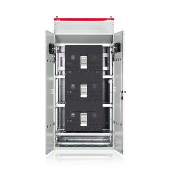
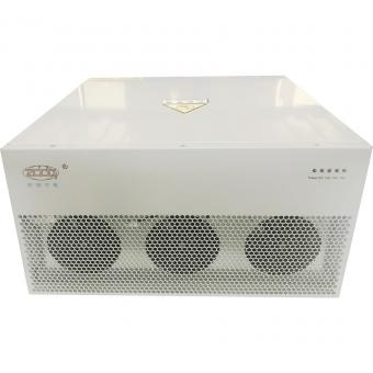
Optimal solution: Install a standard capacitor compensation cabinet
By using high-load low-load compensation or no-load direct compensation for capacitor switching, the inductive reactive power shortfall of the transformer under no-load conditions is made up, accurately covering light-load and no-load conditions. No excessive compensation is required under load, and precise compensation is provided under no-load conditions, perfectly solving the problem of insufficient reactive power in small power plants, with extremely high cost perfomance.

Scenario 2: Numerous charging stations, capacitive reactive power > transformer no-load inductive reactive power
Large charging stations and charging piles are densely distributed, resulting in an extremely large amount of standby capacitive reactive power, far exceeding the no-load inductive reactive power of transformers. At this time, the power grid is in a state of strong capacitive and over-compensated leading, rendering ordinary capacitor banks completely ineffective.
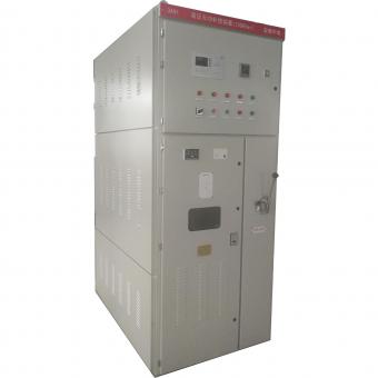
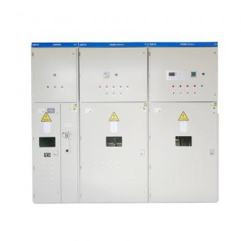
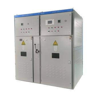
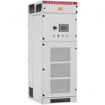
Optimal solution: Install SVG or dedicated reactor
Only SVG dynamic compensation devices, or time-domain electronic bidirectional reactive power compensation controllers combined with dedicated reactors, can absorb excess capacitive reactive power and reverse balance the power grid. They can identify the capacitive and inductive states of the power grid in real time, dynamically adjust bidirectionally, and completely solve the problem of overcompensation during standby at dense charging stations.

IV. Conclusion: When considering charging station compensation, avoid blindly following trends.
1. Load does not exceed the limit : The charging pile charges normally and has built-in power factor correction, so no additional compensation is required;
2. No-load operation inevitably leads to failure : Standby capacitive reactive power is the core culprit for charging station fines;
3. Small stations are inductive : with few charging piles and weak capacitance, ordinary capacitor banks are used to compensate for the no-load reactive power of the transformer;
4. Large stations are capacitive : With many piles and strong capacitive properties, SVG/reactors must be used to absorb excess capacitive reactive power.
Many charging station penalties for reactive power failure are not due to equipment malfunction, but rather to compensation schemes that are incompatible with operating conditions. Only by selecting appropriate equipment and implementing precise management can we completely eliminate penalties for reactive power failure under no-load conditions.


NO.25,JINHE RD,HUAIYUAN ECONOMIC DEVELOPMENT ZONE ,BENGBU,ANHUI
Scan to WhatsApp: