Applications:
Networks which have a wide range of power factor requirements, from leading to lagging, which require fast switching and dynamic compensation, are well suited to correction via a STATCOM.

Features
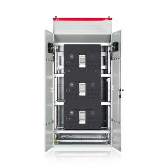
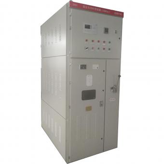
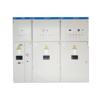
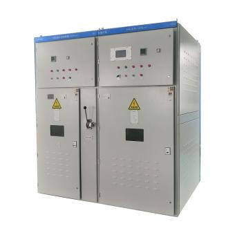
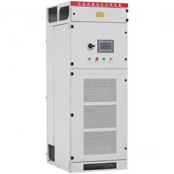
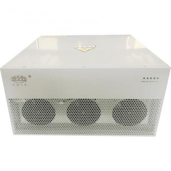
Static Var Generator SVG
As discussed earlier, the Power Factor Correction environment today is requiring solutions which are more dynamic in nature,and can respond to quickly changing loads and requirements.One device which can respond to these requirements is a StaticVar Generator (SVG).
A SVG is a piece of equipment designed to respond quickly and dynamically to changes in reactive power requirements. The SVG has a similar operating principle to an active harmonic filter. The SVG will detect a lagging current within the load by detecting the phase angle difference, and inject into the network a current of the same magnitude, but of opposite polarity (ie. 180° out of
phase) to the current waveform in the network. This is shown below in figure – if the load current is lagging the load voltage, the SVG will inject a capacitive (ie. leading) current into the network to create system balance.

A SVG has many advantages over a capacitor based system.The SVG can respond to a wide range of power factor issues,from leading to lagging, and does so dynamically, mapping the kVAr requirements and providing power factor over 0.99.
This is shown in following figure.

SVGs have a much faster response time than capacitor banks.As they often require pulling in capacitors via contactors, the response time is much slower –Traditional Power Factor Correction can and should be set in at least tens of seconds or minutes to avoid excess switching of capacitors. Capacitor banks are also unable to correct for reactive imbalance across each phase. This capability is inbuilt with the SVG, as it corrects each phase individually (when used in a 4-wire configuration).
The performance of the SVG is virtually unaffected by low
voltage grid levels, unlike a capacitor, which as described earlier, varies its reactive power output depending on the voltage. As well as this, the SVG eliminates the possibility of introducing a resonant condition into the network, as opposed to capacitors.
SVG technology also has a greater service life than capacitor based systems. Capacitor banks require replacement of capacitors as they deplete over time. Alongside this, constant switching and high inrush currents expose the contactors of capacitor based systems to a high level of wear, and these must also be regularly replaced. The maintenance schedule for a capacitor based system is also recommended to be undertaken every 3 months. This leads to costly shutdown times and long-term maintenance issues and requirements, leading to higher overall costs. The SVG offers a system with minimal maintenance required, roughly once every 12 months.
FeaturesCorrect power factor to>0.98
Dynamic,step-less reactive power compensation
Provide correction over the entire power factor range, from -1 to +1 power factor
Fast Response time<10ms
Load balancing capabilities
Power factor correction across multiple phases
Low maintenance requriements.


NO.25,JINHE RD,HUAIYUAN ECONOMIC DEVELOPMENT ZONE ,BENGBU,ANHUI
Scan to WhatsApp: