Harmonic Interference and Solutions in Variable Frequency Systems
May 06,2026
With the development of industrial automation technology, frequency converters are being used more and more widely. Their excellent speed regulation performance and obvious energy-saving effect are increasingly praised. However, the harmonics generated by frequency converters during operation are causing more and more serious damage to the power grid. Therefore, the requirements for suppressing harmonic interference and improving power quality are becoming more and more urgent.
Principle of frequency converter
A frequency converter is a device that converts AC power with a fixed voltage and frequency into AC power with variable voltage and frequency. The main circuit is generally AC-DC-AC. A three-phase bridge rectifier circuit rectifies the 380V/50Hz power frequency AC power into DC voltage, and then inverts it into AC voltage with variable frequency through capacitor filtering and high-power switching elements (IGBT, GTO, etc.).
Harmonics injected into the power grid will cause additional temperature rise and insulation damage to inductive equipment such as motors, transformers, and wires, resulting in a shortened lifespan of electrical equipment, increased losses, capacitor failures and damage, and an increased likelihood of system resonance. Harmonics may also cause a series of problems such as malfunction of relay protection and automatic devices, inaccurate instrument readings and power metering, and interference with communication systems.
harmonics of frequency converters
As can be seen from the principle of frequency converters, due to the switching characteristics of the inverter circuit, the frequency converter forms a typical nonlinear load on the power supply circuit. When current flows through the load, it is not linearly related to the applied voltage, thus forming a non-sinusoidal current and generating harmonics. Both the input and output voltages and currents of the frequency converter contain many high-order harmonic components.
Waveform on the output side of the frequency converter
In the inverter output circuit, both the output voltage and current contain harmonics. For PWM-controlled inverters, as long as it is a voltage-type inverter, regardless of the type of PWM control, its output voltage waveform is a rectangular wave, where the harmonic frequencies are related to the inverter's modulation frequency. The current waveform is an approximate sine wave with glitches.
High-order harmonic hazards
1. Transformers: Harmonic currents and voltages increase copper and iron losses in transformers, resulting in increased transformer temperature, reduced insulation capacity, and decreased capacity margin. Harmonics can also generate resonance and noise.
2. Induction Motors: Harmonics also increase copper and iron losses in the motor, leading to increased temperature. Simultaneously, harmonic currents alter the electromagnetic torque, generating vibrational torque that causes periodic speed fluctuations in the motor, affecting output efficiency and producing noise.
Another argument is that harmonics cause additional heating in the motor, leading to an extra temperature rise; increase repetitive peak voltage, damaging the motor's insulation and reducing its lifespan; generate torque pulsation; and increase noise. In practical applications, many unexplained motor failures are caused by harmonics. A sine wave filter can be used to improve the waveform at the inverter's output, correcting the output waveform to a perfect sine wave.
3. Switching equipment: Harmonic currents cause a high rate of current change in switching equipment at startup, which increases the transient recovery peak voltage, damages insulation, and can also cause the switch to trip or malfunction.
4. Protective Electrical Appliances:Harmonics in the current of protective electrical appliances can generate additional torque, altering their operating characteristics, causing malfunctions, or even burning out coils.
5. Metering Instruments:Harmonics in metering instruments can cause additional torque in the induction plate, leading to errors, reduced accuracy, or even burning out coils.
6. Power Electronic Equipment:Power electronic equipment typically relies on the principle of precise power supply zero-crossing or the shape of voltage waveforms for control and operation. If the voltage contains harmonic components, zero-crossing shifts, waveform changes, and numerous malfunctions can occur. Computers and some other electronic devices typically require a total harmonic distortion (THD) of less than 5%, and individual harmonic distortion rates of less than 3%. Higher distortion can lead to control equipment malfunctions, resulting in production or operational interruptions and significant economic losses.
7. Power Cables:High-frequency harmonic currents can induce the skin effect in conductors, generating additional temperature rise and increasing copper losses. In particular, the zero-sequence third harmonic currents superimpose in the neutral line, resulting in a very large neutral line current in the power supply system. In some cases, the current on the neutral line may even exceed the phase current, causing the neutral line to heat up, accelerating insulation aging, and even causing a fire. Furthermore, when there is a large harmonic current on the neutral line, the conductor impedance can generate a large neutral line voltage drop, interfering with the normal operation of various microelectronic systems.
8.Power Capacitors:Due to the increased frequency of higher harmonics, the impedance of capacitors to higher harmonics decreases, leading to overheating due to overcurrent, and even damage to the capacitors. Parallel or series circuits formed by capacitors and inductive loads in the system may also experience harmonic resonance, amplifying harmonic currents or voltages and exacerbating the harmful effects of harmonics. Parallel resonant circuits formed by the capacitor bank capacitance and the grid inductance can be amplified by 10-15 times.
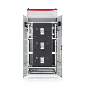
Methods for Suppressing Harmonics in Frequency Converters
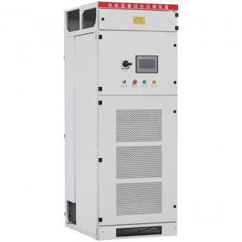
An active harmonic filter is essentially a harmonic generator, connected in parallel or series in the main circuit. It uses a high-speed DSP chip to monitor system parameters in real time, separating the fundamental and harmonic components. A compensation device then outputs a compensation current equal in magnitude and opposite in direction to the harmonic current, achieving real-time compensation for the harmonic current. Compared to passive filters, it offers high controllability and fast response, is unaffected by system impedance, avoids resonance hazards, and can automatically track and compensate for changing harmonics. Its disadvantages include high cost and difficulty in manufacturing large-capacity filters.