What's the Definition of Power Factor?
-
Power Factor Definition: Power factor(PF for short) is the ratio between KW and KVA drawn by an electrical load where the KW is the actual load power and the KVA is the apparent load power. It is a measure of how effectively the current is being converted into useful work output and more particularly is a good indicator of the effect of the load current on the efficiency of power grid system.
-
All current flow causes losses both in the supply and distribution system. A load with a PF of 1.0 results in the most efficient loading of the supply. A load with a PF of, e.g., 0.75, results in much higher losses and a higher electricity bill penalty. An improvement in p can bring about a significant reduction in losses since losses are proportional to the square of the current.
-
When the power factor is less than one the ‘missing’ power is known as reactive power which unfortunately is necessary to provide a magnetizing field required by motors and other inductive loads to perform their desired functions. Reactive power can also be interpreted as wattles, magnetizing or wasted power and it represents an extra burden on the electricity system and on the consumer’s electricity bill.
-
A poor power factor is usually the result of a significant phase difference between the voltage and current at the load terminals, or it can be due to a high harmonic content or a distorted current waveform.
-
A poor power factor is generally the result of an inductive load such as an induction motor, a power transformer, and ballast in a luminary, a welding set or an induction furnace. A distorted current waveform can be the result of a rectifier, an inverter, a variable speed drive, a switched mode power supply, discharge lighting or other electronic loads.
-
A poor power factor due to inductive loads can be improved by the addition of power factor correction equipment, but a poor power factor due to a distorted current waveform requires a change in equipment or the addition of harmonic filters.
-
Some inverters are quoted as having a power factor of better than 0.95 when, in reality, the true power factor is between 0.5 and 0.75. The figure of 0.95 is based on the cosine of the angle between the voltage and current but does not take into account that the current waveform is discontinuous and therefore contributes to increased losses.
-
An inductive load requires a magnetic field to operate and in creating such a magnetic field causes the current to be out of phase with the voltage (the current lags the voltage). Power factor correction is the process of compensating for the lagging current by creating a leading current by connecting capacitors to the supply.
-
P.F (Cos Ǿ)= K.W / KVA Or
-
P.F (Cos Ǿ)= True Power / Apparent Power.
-
KW is Working Power (also called Actual Power or Active Power or Real Power).
-
It is the power that actually powers the equipment and performs useful work.
-
KVAR is Reactive Power.
-
It is the power that magnetic equipment (transformer, motor and relay)needs to produce the magnetizing flux.
-
KVA is Apparent Power.
-
It is the “vectorial summation” of KVAR and KW.
Displacement Power Factor Correction
An induction motor draws current from the supply that is made up of resistive components and inductive components. The resistive components are:
1) Load current.
2) Loss current.
And the inductive components are:
3) Leakage reactance.
4) Magnetizing current.

-
The current due to the leakage reactance is dependent on the total current drawn by the motor, but the magnetizing current is independent of the load on the motor. The magnetizing current will typically be between 20% and 60% of the rated full load current of the motor. The magnetizing current is the current that establishes the flux in the iron and is very necessary if the motor is going to operate.
-
The magnetizing current does not actually contribute to the actual work output of the motor. It is the catalyst that allows the motor to work properly. The magnetizing current and the leakage reactance can be considered passenger components of current that will not affect the power drawn by the motor, but will contribute to the power dissipated in the supply and distribution system.
-
Take for example a motor with a current draw of 100 Amps and a power factor of 0.78. The resistive component of the current is 78 Amps and this is what the KWh meter measures. The higher current will result in an increase in the distribution losses of (100 x 100) /(78 x 78) = 1.65 or a 65% increase in the supply losses.
-
In the interest of reducing the losses in the distribution system, power factor correction is added to neutralize a portion of the magnetizing current of the motor. Typically, the corrected power factor will be 0.92 – 0.95
-
Power factor correction is achieved by the addition of capacitors in parallel with the connected motor circuits and can be applied at the starter, or applied at the switchboard or distribution panel. The resulting capacitive current is leading current and is used to cancel the lagging inductive current flowing from the supply.

Displacement Static Correction (Static Compensation).
-
As a large proportion of the inductive or lagging current on the supply is due to the magnetizing current of induction motors, it is easy to correct each individual motor by connecting the correction capacitors to the motor starters.
-
With static correction, it is important that the capacitive current is less than the inductive magnetizing current of the induction motor. In many installations employing static power factor correction, the correction capacitors are connected directly in parallel with the motor windings.
-
When the motor is Off Line, the capacitors are also Off Line. When the motor is connected to the supply, the capacitors are also connected providing correction at all times that the motor is connected to the supply. This removes the requirement for any expensive power factor monitoring and control equipment.
-
In this situation, the capacitors remain connected to the motor terminals as the motor slows down. An induction motor, while connected to the supply, is driven by a rotating magnetic field in the stator which induces current into the rotor. When the motor is disconnected from the supply, there is for a period of time, a magnetic field associated with the rotor. As the motor decelerates, it generates voltage out its terminals at a frequency which is related to its speed.
-
The capacitors connected across the motor terminals, form a resonant circuit with the motor inductance. If the motor is critically corrected, (corrected to a power factor of 1.0) the inductive reactance equals the capacitive reactance at the line frequency and therefore the resonant frequency is equal to the line frequency. If the motor is over corrected, the resonant frequency will be below the line frequency. If the frequency of the voltage generated by the decelerating motor passes through the resonant frequency of the corrected motor, there will be high currents and voltages around the motor/capacitor circuit. This can result in severe damage to the capacitors and motor. It is imperative that motors are never over corrected or critically corrected when static correction is employed.
-
Static power factor correction should provide capacitive current equal to 80% of the magnetizing current, which is essentially the open shaft current of the motor.
-
The magnetizing current for induction motors can vary considerably. Typically, magnetizing currents for large two pole machines can be as low as 20% of the rated current of the motor while smaller low speed motors can have a magnetizing current as high as 60% of the rated full load current of the motor
-
Where the open shaft current cannot be measured, and the magnetizing current is not quoted, an approximate level for the maximum correction that can be applied can be calculated from the half load characteristics of the motor. It is dangerous to base correction on the full load characteristics of the motor as in some cases, motors can exhibit a high leakage reactance and correction to 0.95 at full load will result in over correction under no load, or disconnected conditions.
-
Static correction is commonly applied by using on e contactor to control both the motor and the capacitors. It is better practice to use two contactors, one for the motor and one for the capacitors. Where one contactor is employed, it should be up sized for the capacitive load. The use of a second contactor eliminates the problems of resonance between the motor and the capacitors.
How Capacitors Banks Work
-
Induction motors, transformers and many other electrical loads require magnetizing current (kvar) as well as actual power (kW). By representing these components of apparent power (kVA) as the sides of a right triangle, we can determine the apparent power from the right triangle rule: kVA2 = kW2 + kVAR2.
-
To reduce the kva required for any given load, you must shorten the line that represents the kvar,which is precisely supplied by capacitors. By providing kvar right to the load, the capacitors relieve the utility of the burden of carrying the extra kvar. This makes the utility transmission/distribution system more efficient, reducing cost for the utility and their customers. The ratio of actual power to apparent power is usually expressed in percentage and is called power factor.
What Causes Lower Power Factor?
-
we see that low power factor results when KW is small in relation to KVA. Inductive loads. Inductive loads (which are sources of Reactive Power) include:
-
Power Transformers
-
Induction motor
-
Induction generators (mill generators)
-
High intensity discharge lighting
-
Variable Frequency drives
-
These inductive loads constitute a major portion of the power consumed in industrial complexes.
-
Reactive power (KVAR) required by inductive loads increases the amount of apparent power (KVA) in your distribution system .This increase in reactive and apparent power results in a larger angle (between KW and KVA).
Why Should we Improve our Power Factor?
-
Some of the benefits of improving your power factor include:
1) Lower utility fees by:
A. Reducing peak KW billing demand:
-
Inductive loads, which require reactive power, caused your low power factor. This increase in required reactive power (KVAR) causes an increase in required apparent power (KVA), which is what the utility is supplying. So, a load's low power factor causes the utility to have to increase its generation and transmission capacity in order to handle this extra demand.
-
By lowering your power factor, you use less KVAR. This results in less KW, which equates to a dollar savings from the utility.
B. Eliminating the power factor penalty:
-
Utilities usually charge customers an additional fee when their power factor is less than 0.95. (In fact, some utilities are not obligated to deliver electricity to their customer at any time the customer’s power factor falls below 0.85.) Thus, you can avoid this additional fee by increasing your power factor.
2) Increased voltage level in your power gird system and cooler, more efficient motors
-
Uncorrected power factor causes power system losses in your distribution system. As power losses increase, you may experience voltage drops. Excessive voltage drops can cause overheating and premature failure of motors and other inductive equipment. So, by raising your power factor, you will minimize these voltage drops along feeder cables and avoid related problems. Your motors will run cooler and be more efficient, with a slight increase in capacity and starting torque.
3) Increased system capacity and reduced system losses in power grid system
-
By adding capacitors (KVAR generators) to grid, the power factor is improved and the KW capacity of the grid is increased.
-
For example, a 1,000 KVA transformer with an 80% power factor provides 800 KW (600 KVAR) of power to the main bus.
-
By increasing the power factor to 90%, more KW can be supplied for the same amount of KVA.
-
1000 KVA2 = (900 KW)2 + ( ? KVAR)2 Acoording to S*S=P*P+Q*Q
-
KVAR = 436
-
The KW capacity of the system increases to 900 KW and the utility supplies only 436 KVAR.
-
Uncorrected power factor causes power system losses in your distribution system. By improving your power factor, these losses can be reduced. With the current rise in the cost of energy, increased facility efficiency is very desirable. And with lower system losses, you are also able to add additional load to your system.
Automatic Power Factor Correction (APFC) Panel
Power Factor improvement:
-
Please check if required kVAr of capacitors are installed.
-
Check the type of capacitor installed is suitable for application or the capacitors are rated or not.
-
Check if the capacitors are permanently ‘ON’. The Capacitor are not switched off
-
when the load is not working, under such condition the average power factor is found to be lower side.
-
Check whether all the capacitors are operated in APFC depending upon the load operation.
-
Check whether the APFC installed in the installation is working or not. Check the CT connection is taken from the main incomer side of transformer, after the fix compensation of transformer.
-
Check if the load demand in the system is increased.
-
Check if power transformer compensation is provided.
Thumb Rule if HP is known.
-
The compensation for motor should be calculated taking the details from the rating plate of motor Or
-
the capacitor should be rated for 1/3 of HP
Kvar Required For Transformer Compensation:
Transformer Required Kva
-
<= 315 kVA T.C = 5% of KVA
-
315kVA To 1000 kVA = 6% of KVA
-
>= 1000 kVA = 8% of KVA
Where to connect capacitor:
-
Fix compensation should be provided to take care of power transformer. Power and distribution transformers, which work on the principle of electro-magnetic induction, consume reactive power for their own needs even when its secondary is not connected to any load. The power factor will be very low under such situation. To improve the power factor it is required to connect a fixed capacitor bank at the low voltage side of the Transformer. For approximate kVAr of capacitors required
-
If the installation is having various small loads with the mixture of large loads then the APFC should be recommended. Note that APFC should have minimum step rating of 10% as smaller step.
-
If loads are small then the capacitor should be connected parallel to load. The connection should be such that whenever the loads are switched on the capacitor also switches on along with the load.
-
Note that APFC panel can maintain the power factor on LV side of transformer and it is necessary to provide fix compensation for Power transformer.
-
In case there is no transformer in the installation, then the C.T for sensing power factor should be provided at the incoming of main switch of the plant.
Calculation of required capacitor:
-
Suppose Actual P.F is 0.8, Required P.F is 0.98 and Total Load is 516KVA.
-
Power factor = kwh / kvah
-
kW = kVA x Power Factor
-
= 516 x 0.8 = 412.8
-
Required capacitor = kW x Multiplying Factor
-
= (0.8 x 516) x Multiplying Factor
-
= 412.8 x 0.547 (See Table to find Value according to P.F 0.8 to P.F of 0.98)
-
= 225.80 kVar
-
Any problem, contact with us, we can acculate and design for you.
Multiplying factor for calculating kVAr
Target PF
|
0.6
|
0.9
|
0.91
|
0.92
|
0.93
|
0.94
|
0.95
|
0.96
|
0.97
|
0.98
|
0.99
|
1
|
|
0.6
|
0.849
|
0.878
|
0.907
|
0.938
|
0.970
|
1.005
|
1.042
|
1.083
|
1.130
|
1.191
|
1.333
|
|
0.61
|
0.815
|
0.843
|
0.873
|
0.904
|
0.936
|
0.970
|
1.007
|
1.048
|
1.096
|
1.157
|
1.299
|
|
0.62
|
0.781
|
0.810
|
0.839
|
0.870
|
0.903
|
0.937
|
0.974
|
1.015
|
1.062
|
1.123
|
1.265
|
|
0.63
|
0.748
|
0.777
|
0.807
|
0.837
|
0.870
|
0.904
|
0.941
|
0.982
|
1.030
|
1.090
|
1.233
|
|
0.64
|
0.716
|
0.745
|
0.775
|
0.805
|
0.838
|
0.872
|
0.909
|
0.950
|
0.998
|
1.058
|
1.201
|
|
0.65
|
0.685
|
0.714
|
0.743
|
0.774
|
0.806
|
0.840
|
0.877
|
0.919
|
0.966
|
1.027
|
1.169
|
|
0.66
|
0.654
|
0.683
|
0.712
|
0.743
|
0.775
|
0.810
|
0.847
|
0.888
|
0.935
|
0.996
|
1.138
|
|
0.67
|
0.624
|
0.652
|
0.682
|
0.713
|
0.745
|
0.779
|
0.816
|
0.857
|
0.905
|
0.966
|
1.108
|
|
0.68
|
0.594
|
0.623
|
0.652
|
0.683
|
0.715
|
0.750
|
0.787
|
0.828
|
0.875
|
0.936
|
1.078
|
|
0.69
|
0.565
|
0.593
|
0.623
|
0.654
|
0.686
|
0.720
|
0.757
|
0.798
|
0.846
|
0.907
|
1.049
|
|
0.7
|
0.536
|
0.565
|
0.594
|
0.625
|
0.657
|
0.692
|
0.729
|
0.770
|
0.817
|
0.878
|
1.020
|
|
0.71
|
0.508
|
0.536
|
0.566
|
0.597
|
0.629
|
0.663
|
0.700
|
0.741
|
0.789
|
0.849
|
0.992
|
|
0.72
|
0.480
|
0.508
|
0.538
|
0.569
|
0.601
|
0.635
|
0.672
|
0.713
|
0.761
|
0.821
|
0.964
|
|
0.73
|
0.452
|
0.481
|
0.510
|
0.541
|
0.573
|
0.608
|
0.645
|
0.686
|
0.733
|
0.794
|
0.936
|
|
0.74
|
0.425
|
0.453
|
0.483
|
0.514
|
0.546
|
0.580
|
0.617
|
0.658
|
0.706
|
0.766
|
0.909
|
|
0.75
|
0.398
|
0.426
|
0.456
|
0.487
|
0.519
|
0.553
|
0.590
|
0.631
|
0.679
|
0.739
|
0.882
|
|
0.76
|
0.371
|
0.400
|
0.429
|
0.460
|
0.492
|
0.526
|
0.563
|
0.605
|
0.652
|
0.713
|
0.855
|
|
0.77
|
0.344
|
0.373
|
0.403
|
0.433
|
0.466
|
0.500
|
0.537
|
0.578
|
0.626
|
0.686
|
0.829
|
|
0.78
|
0.318
|
0.347
|
0.376
|
0.407
|
0.439
|
0.474
|
0.511
|
0.552
|
0.599
|
0.660
|
0.802
|
|
0.79
|
0.292
|
0.320
|
0.350
|
0.381
|
0.413
|
0.447
|
0.484
|
0.525
|
0.573
|
0.634
|
0.776
|
|
0.8
|
0.266
|
0.294
|
0.324
|
0.355
|
0.387
|
0.421
|
0.458
|
0.499
|
0.547
|
0.608
|
0.750
|
|
0.81
|
0.240
|
0.268
|
0.298
|
0.329
|
0.361
|
0.395
|
0.432
|
0.473
|
0.521
|
0.581
|
0.724
|
|
0.82
|
0.214
|
0.242
|
0.272
|
0.303
|
0.335
|
0.369
|
0.406
|
0.447
|
0.495
|
0.556
|
0.698
|
|
0.83
|
0.188
|
0.216
|
0.246
|
0.277
|
0.309
|
0.343
|
0.380
|
0.421
|
0.469
|
0.530
|
0.672
|
|
0.84
|
0.162
|
0.190
|
0.220
|
0.251
|
0.283
|
0.317
|
0.354
|
0.395
|
0.443
|
0.503
|
0.646
|
|
0.85
|
0.135
|
0.164
|
0.194
|
0.225
|
0.257
|
0.291
|
0.328
|
0.369
|
0.417
|
0.477
|
0.620
|
|
0.86
|
0.109
|
0.138
|
0.167
|
0.198
|
0.230
|
0.265
|
0.302
|
0.343
|
0.390
|
0.451
|
0.593
|
|
0.87
|
0.082
|
0.111
|
0.141
|
0.172
|
0.204
|
0.238
|
0.275
|
0.316
|
0.364
|
0.424
|
0.567
|
|
0.88
|
0.055
|
0.084
|
0.114
|
0.145
|
0.177
|
0.211
|
0.248
|
0.289
|
0.337
|
0.397
|
0.540
|
|
0.89
|
0.028
|
0.057
|
0.086
|
0.117
|
0.149
|
0.184
|
0.221
|
0.262
|
0.309
|
0.370
|
0.512
|
|
0.9
|
|
0.029
|
0.058
|
0.089
|
0.121
|
0.156
|
0.193
|
0.234
|
0.281
|
0.342
|
0.484
|
|
0.91
|
|
|
0.030
|
0.060
|
0.093
|
0.127
|
0.164
|
0.205
|
0.253
|
0.313
|
0.456
|
|
0.92
|
|
|
|
0.031
|
0.063
|
0.097
|
0.134
|
0.175
|
0.223
|
0.284
|
0.426
|
|
0.93
|
|
|
|
|
0.032
|
0.067
|
0.104
|
0.145
|
0.192
|
0.253
|
0.395
|
|
0.94
|
|
|
|
|
|
0.034
|
0.071
|
0.112
|
0.160
|
0.220
|
0.363
|
|
0.95
|
|
|
|
|
|
|
0.037
|
0.078
|
0.126
|
0.186
|
0.329
|
Test of Capacitor at Site:
Measurement of Voltage:
-
Check the voltage using multi meter at capacitor terminals.
-
Please note that the current output of 440 volt capacitor connected to a system of 415 volt will be lesser than rated value.
-
Table no -1 & 2give you the resultant kVAr output of the capacitor due to variation in supply voltage.
-
The kVAr of capacitor will not be same if voltage applied to the capacitor and frequency changes. The example given below shows how to calculate capacitor current from the measured value at site.
-
Example :
-
1. Name plate details – 15kVAr, 3 phases, 440v, and 50Hz capacitor.
-
Measured voltage – 425v , Measured frequency – 48.5Hz
-
Kvar = (fM / fR) x (VM / VR)2 x kvar
-
Kvar = (48.5/50) x (425 / 440)2 x 15
-
= 13.57kVAr.
-
2. Name plate details – 15kVAr, 3 phases, 415v, and 50Hz capacitor.
-
Measured voltage – 425v, Measured frequency – 48.5Hz
-
Kvar = (fM / fR) x (VM / VR)2 x kVAr
-
Kvar = (48.5/50) x (425 / 415)2 x 15
-
= 15.26kVAr
Three Phase 440V Capacitor
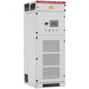
|
kVAr 440V
|
Line current 440V
|
kVAr at 415V
|
Line Current at 415V
|
Measured capacitance across two terminals with third terminal open.(Micro farad) 440V
|
|
5
|
6.56
|
4.45
|
6.188
|
41.10
|
|
7.5
|
9.84
|
6.67
|
9.28
|
61.66
|
|
10
|
13.12
|
8.90
|
12.38
|
82.21
|
|
12.5
|
16.4
|
11.12
|
15.47
|
102.76
|
|
15
|
19.68
|
13,34
|
18.56
|
123.31
|
|
20
|
26.24
|
17.79
|
24.75
|
164.42
|
|
25
|
32.80
|
22.24
|
30.94
|
205,52
|
Three Phase 415V Capacitor
|
kVAr 415V
|
Line current 415V
|
kVAr at 440V
|
Line Current at 415V
|
Measured capacitance across two terminals with third terminal open.(Micro farad) 415V
|
|
5
|
6.55
|
5.62
|
7.38
|
46.21
|
|
7.5
|
10.43
|
8.43
|
11.06
|
69.31
|
|
10
|
13.91
|
11.24
|
14.75
|
92.41
|
|
12.5
|
17.39
|
14.05
|
18.44
|
116.51
|
|
15
|
20.87
|
16.86
|
22.13
|
138.62
|
|
20
|
27.82
|
22.48
|
29.50
|
184.82
|
|
25
|
34.78
|
38.10
|
36.88
|
231.03
|
Measurement of Current:
-
The capacitor current can be measured using Multi meter.
-
Make a record of measurement data of individual phase and other parameter.
-
Check whether the current measured is within the limit value with respect to supply voltage & data given in the name plate of capacitor Refer formulafor calculation
-
Formula for calculating rated current of capacitor with rated supply voltage and frequency.
-
l = kvar x 103 / ( 3 X V ) L L
-
Example:
-
15kVAr, 3 phase, 440v, 50Hz capacitor.
-
l = kVAr x 103 / ( 3 X V ) L L
-
l = (15 x 1000) / (1.732 x 440) L
-
l = 19.68AMPs L
-
15kVAr, 3 phases, 415v, 50Hz capacitor
-
l = kVAr x 103/ ( 3 X V ) L L
-
l = (15 x 1000) / (1.732 x 415) L
-
l = 20.87 Amps
Discharge of Capacitor:
-
LV power capacitors are provided with discharge resistor to discharge the capacitor which is limited to one min.
-
Switch off the supply to the capacitor and wait for 1 minute and then short the terminals of capacitor to ensure that the capacitor is completely discharged.
-
This shorting of terminals ensures the safety while handling the capacitor
-
Discharge of capacitor also becomes necessary for the safety of meter used for capacitance measurement.
Termination and Mounting:
-
Use suitable size lugs for connecting the cable to the terminals of capacitor.
-
Ensure that there is no loose connection: As loose connection may lead to failure of capacitor / insulation break down of cable.
-
Use proper tools for connection / tightening.
-
Ensure that the capacitor is mounted vertically.
-
The earthing of capacitor should be done before charging.
-
The applied voltage should not exceed more than 10%. Refer technical specification of capacitor.
-
The capacitor should be provided with the short circuit protection device as indicated in following Table
|
KVAr
|
HRC Fuse
|
Cable Amps
|
|
5
|
12 Amps
|
12 Amps
|
|
7.5
|
25 Amps
|
25 Amps
|
|
10
|
32 Amps
|
32 Amps
|
|
12.5
|
32 Amps
|
32 Amps
|
|
15
|
50 Amps
|
50 Amps
|
|
20
|
50 Amps
|
50 Amps
|
|
25
|
63 Amps
|
63 Amps
|
|
50
|
125 Amps
|
125 Amps
|
|
75
|
200 Amps
|
200 Amps
|
|
100
|
200 Amps
|
250 Amps
|
Capacitor in APFC panel
-
The capacitor should be provided with suitable designed inrush current limiting inductor coils or special capacitor duty contactors. Annexure d point no d-7.1 of IS 13340-1993
-
Once the capacitor is switched off it should not be switched on again within 60 seconds so that the capacitor is completely discharged. The switching time in the relay provided in the APFC panel should be set for 60 seconds for individual steps to discharge. Clause No-7.1 of IS 13340-1993
-
If the capacitor is switched manually or if you are switching capacitors connected in parallel with each other then “ON” delay timer (60sec) should be provided and in case of parallel operation once again point No 1 should be taken care. Clause No-7.1 of IS 13340-1993
-
The capacitor mounted in the panel should have min gap of 25-30 mm between the capacitor and 50 mm around the capacitor to the panel enclosure.
-
In case of banking a min gap of 25mm between the phase to phase and 19mm between the phases to earth should be maintained. Ensure that the banking bus bar is rated for 1.8 times rated current of bank.
-
The panel should have provision for cross ventilation, the louver / fan can be provided in the care Annexure d point No d-3.1 IS 13340-1993
-
For use of reactor and filter in the panel fan should be provided for cooling.
-
Short circuit protection device (HRC fuse / MCCB) should not exceed 1.8 x rated current of capacitor.
-
In case of detuned filter banks MCCB is recommended for short circuit protection.
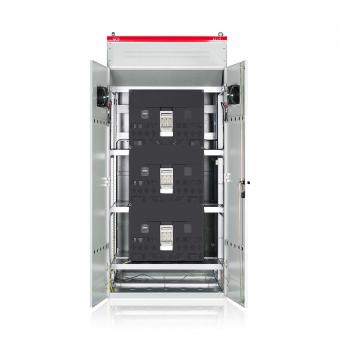
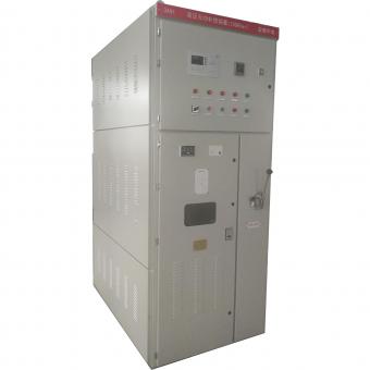
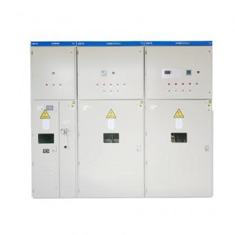
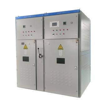
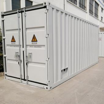
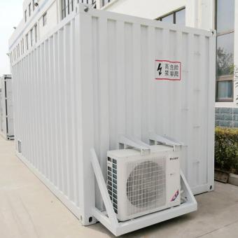
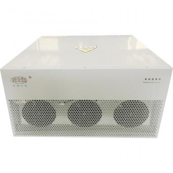
ZDDQ APFC Panel
Low voltage APFC Panel
High Voltage APFC Panel