Abstract: The application of SVG/STATCOM, a high voltage dynamic reactive power compensation device, produced by ZDDQ Electric Co., Ltd. is described in this paper. Its role in reactive power compensation for new energy construction is analyzed and its applications in electric and electronic fields are indicated.
Key words: SVG;STATCOM; Photovoltaic station; Reactive power compensation; Application

1 Introduction
As global economy grows, development and utilization of new energies including PV generation and wind plant is an effective solution to energy shortage crisis and heavy environmental pressure, two problems that concern the world. Large PV stations and grid-connected roof-top PV systems are promising trends for utilization of solar energy. Rapid development of PV generation also brings about many new problems, among which, reactive voltage is one of the most worrying. PV system is dependent on light intensity and temperature, changes in which cause fluctuation of voltage at grid connection point. Connection of large PV stations to the grid exerts further influence on the safe and stable operation of grid, especially the sudden disconnection of PV stations in the event of grid failure further worsens the grid operation. As more and larger PV stations are put into production, technical problems relating to PV stations, for example, sudden disconnection from the grid, will be increasingly concerned.
2 Critical Problems to be Solved for PV Stations
In the case of high penetration or increased output of PV stations, the grid is prone to failure, which causes PV station trip. A certain time is needed to re-connect PV stations to the grid after recovery. The power shortage caused in this period results in trip of adjacent PV stations, causing the outage in a large area and affecting grid safety and stability.
To this end, it is important to enable existing PV stations to stay connected in short period of lower grid voltage. Proper controlling the low voltage ride through of large PV stations can guarantee their stable and safe operation after connected to grid. Low voltage ride through is seldom possible in PV stations, either in China or in abroad, due to reactive power output. The bottleneck that restricts PV station’s low voltage ride through lies in the current outputted at inverter’s AC side. If the output exceeds its rated value by a large margin, electrical and electronic comments will be damaged. For this reason, Statcom or other similar devices are installed at PV station buses to compensate the reactive power and enable power stations to stay connected and to output a certain reactive power to the grid for maintain the voltage at grid connection point, in the event of grid outrage, a mechanism that mitigates the adverse effect of sudden disconnection of PV stations on the grid.
3 Necessity of STATACOM Installation
A static synchronous compensator Statcom (also as konwn static var generator SVG) is able to rapidly and smoothly adjust reactive power, provide dynamic voltage support and improve system’s operating performance. By installing an Statcom at the outlet of a PV station and controlling the reactive power compensated by STATCOM based on the deviation of voltage at the grid connection point, one can stabilize grid voltage at the PV station and lower the influence of power fluctuation on grid voltage. In the case of system short circuit, with its dynamic reactive power adjusting ability, statcom can speed up the recovery process for PV station’s internal and grid connection point voltages after the short circuit is removed. In the case of load change, STATCOM can effectively lower PV station’s voltage change, being helpful for safe operation of PV station and stability of electricity quality.
A statcom is able to rapidly and smoothly adjust reactive power, provide dynamic voltage support and improve system’s operating performance

In the case of system short circuit, with its dynamic reactive power adjusting ability, Statcom can speed up the recovery process for PV station’s internal and grid connection point voltages after the short circuit is removed. In the case of load change, Statcom can effectively lower PV station’s voltage change, being helpful for safe operation of PV station equipment and stability of electricity quality.
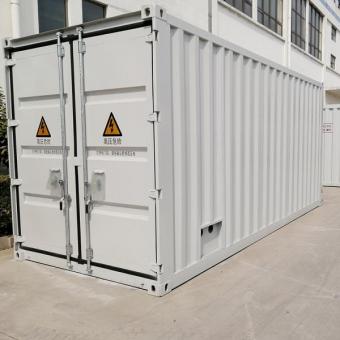
4 Project Overview
State Grid’s 40MWp floating solar farm on Sanlihe reservoir, Zhuxiang Town, Changfeng County was proposed to use 2*79200 polysilicon assemblies, each of which is 225Wp. The total capacity is designed to be 40.392MW provided by 2*1920 solar panels in an array. 20 panels form a string; in this way, there are 3960*2 strings. In the farm 64 inverters connected to the grid and 32 x 1250kVA transformers would be installed. The project’s expected annual generation capacity is 44 million kilowatt-hours after put into production. This project can adjust local electricity structure, help local government complete the emission reduction task, improve people’s life quality and promote sustainable development of local economy.
To increase grid voltage stability and lower large scale PV station’s impact on the grid, low voltage ride through becomes a prerequisite. Large scale PV stations are weak in low voltage ride through if they are solely dependent on PV converters. According to Q/GDW 6127-2011 Technical rule for connecting photovoltaic power stations to power grid, “large and middle scale PV stations must be equipped with voltage control system for reactive power to properly control reactive power and voltage. Subject to electricity dispatching authority’s commands, a PV station’s automatic regulator supplys (or absorbs) reactive power, a way to control the grid connection point voltage within normal range; the adjusting speed and precision must comply with voltage adjustment requirement for electricity system. During low voltage ride through, a PV station had better provide dynamic reactive power support.” Article 5.2 of GB/T29321-2012 Technical specification for reactive power compensation of PV power station specifies that “reactive power compensation devices for PV stations must be able to track output fluctuations of PV stations and system voltage requirement, and respond quickly within 30 ms.” Owner of the PV station in this project selected HVSVG-C9.0/35T, a large scale high voltage dynamic reactive power compensation and harmonics suppression device, manufactured by WindSun, in a bidding process. The device was installed in the PV station for compensating grid’s reactive power and suppression harmonics. After only one attempt, the device was put into production successfully and provided the expected performance.
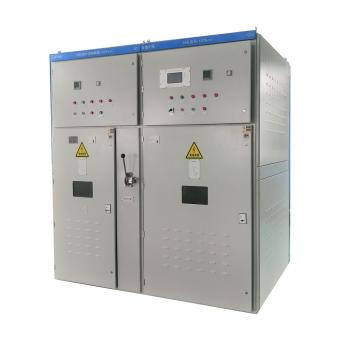
5 ZDDQ 35kv STATCOM HVSVG-C9.0/35T
5.1 HVSVG’s technical strengths
With modern electric and electronic technologies, automation, microelectronics and networked communication, cutting-edge instantaneous reactive power theory and synchronous reference frame transformation-based power decoupling algorithm HVSVG series is aimed to provide the required nature and quantity of reactive power, power factor and grid voltage, dynamically tract the changes in grid electricity quality in order to adjust reactive output, and ensures required operating curves, thereby improving grid quality. This compensation device, based on voltage source type PWM inverter, has fundamentally changed the way in which reactive power compensation is provided. Instead of using large capacity capacitors and inductors, it transforms reactive energy by highly frequently switching electronic and electric components.

HVSVG series, which is easy to use and highly reliable with high performance, is specially designed to meet the urgent needs of users for increased power factor of the transmission and distribution grid, reduced harmonics and negative sequence current compensation, with the following characteristics:
● Modular design facilitates installation, commissioning and setting
● Fast dynamic response ≤ 5ms
● The total harmonics distortion (THD) subject to sufficient compensation is≤ 3%.
● To satisfy user's needs to the largest extent, there are several operating modes, i.e., device reactive power mode; targeted point reactive power mode; targeted point power factor mode; targeted point voltage mode and load compensation mode, with targeted values that can be changed in a real-time manner.
● Real-time tracking of load change helps dynamically compensate reactive power, increase system's power factor, immediately control harmonics and compensate negative sequence current, thereby improving the grid's power quality.
● Voltage flickering can be inhibited to improve voltage quality and stable system voltage.
● Deliberately designed circuit parameters allow low heat generation, high efficiency and low operating cost.
● Compact structure requires a small space
● The main circuit is a series chain of H-bridge power units consisting of IGBT circuits; each phase of the main circuit is composed of many same power units; the output is a square wave superimposed from PWM waveforms, approximating a sine waveform, and performing much more similar to the sine waveform after filtered by the output reactor.
● It can automatically adjust carrier frequency by adapting to environmental and power changes.
● Compensation precision is smaller than 0.2A.
● Redundancy and modular design makes the SVG device meet the high reliability requirement of the system.
● Modularized design of power circuit guarantees easy maintenance and good interchangeability.
● Full protections, i.e., over-voltage, under-voltage, over-current, unit over-heating and voltage unbalance, and recording the transient waveform at failure, can help locate the failure point, provide easy maintenance and high operating reliability.
● HMI is designed in the windows operating mode, with its menu and all function keys tailored to computer operation habits. Friendly pages and external ports including RS485 are available, in addition to supporting standard Modbus protocol. Apart from real-time display of digital and analog quantities, inquiry of operating history records and history curves, monitoring of the unit status, inquiry of system information and inquiry of history failures, the device can provide system self-test after powered-on, one-key on/off, time-shared control, oscilloscope (AD channel mandatory wave-recording), and recording of the transient voltage/current at the failure time.
● STATCOM is designed to have interfaces that go with FC, a way that can effectively combine static and dynamic compensation, providing more economical and flexible compensation options. It has 4 FC interfaces, with which, the order in which 4 FC branches are switched on can be predefined given the actual circumstance and FC sates can be monitored in real time manner. This ensures the intelligent control of Statcom+FC.
● No switching transient impulse, no switching surge and no arc restrike exist, and no discharging is needed before switching again.
● DSP from TI and FPGA from ALTERA are utilized for 3-core control. 3 DSPs provide external communication, main control computation and power unit control; and 3 FPGAs play a supporting role in data processing and exchange. Products with this architecture provides a fast response such that only 3.7 ms is required to respond to the change from capacitive power to inductive power.
● The phase sequence in AC system is not a factor that needs consideration when the device is connected to a larger system, which eases the connection work.
● Parallel installation is allowed, which makes it is easy to extend the capacity. Fiber communication used for parallel operation can ensures faster communication and better real-time compensation. Capacity expansion is fairly easy, especially for a site renovation or a site that is not put into production. If the actual power is found inadequate after STATCOM is put into service, it is allowed to expand the capacity by changing power unit instead of removing the entire device. If several devices are installed in a site, it is easy to form an Ethernet or provide master/slave control through high speed fiber optic cables.
5.2 HVSVG-C9.0/35T technical parameters
ZDDQ HVSVG-C9.0/35T technical parameters are detailed in Table 1
Table 1 HVSVG-C9.0/35T Technical Paramters
5.3 System structure
HVSVG’s main circuit is a chained topology, with a modular-based design and a star connection. Each phase is a series of 20 power units, and the star connection is star type.
Signals of control cabinet and power cabinets are separated by fiber optic cables, a reliable way to separate high voltage from low voltage. Significant improvement in the structure of HVSVG series ensures the easier maintenance. Strict anti-interference protection is taken for the control cabinet to prevent the control system against high voltage main circuit. Power unit is improved so that it requires a smaller space, a way to reduce user's investment requirement.
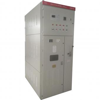
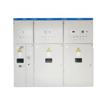
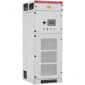
A HVSVG (Statcom) is chiefly comprised of three parts: control-gear, power cabinet and reactor cabinet. The power cabinet is greatly standardized, which provides convenience for capacity extension and stability. HVSVG devices of different voltage levels consist of control cabinet, power cabinets and reactor cabinets (or air core reactors). Main components in each cabinet and their roles are listed in Table 2.
5.3.1 Control-gear
The main circuit includes an isolator switch QS1, a breaker QF, a snubber resistor R, a status detector, etc., as depicted in Figure 1.

Figure 1 Statcom Main Circuit
The standard main control box independently developed by ZDDQ has passed the EMC certification under GB/T17626 and temperature shock and vibration tests, indicating its extremely high reliability.
The control core of the main control box is provided by the synergy computation between a 32-bit high speed digital signal processor (DSP) and a complex programmable logic device (CPLD)/FPGA. Carefully designed algorithm ensures the optimum operating performance of the HVSVG. Large scale integration based controller is manufactured with surface welding technology, ensuring system’s extreme high reliability. Siemens PLC increases system flexibility.
An emergency stop button is placed on the door to facilitate the user to operate in the case of emergency. A friendly HMI from Weinview, a leading Chinese supplier who adopts world-class equipment and standardized operating procedures that are parallel in international standards to ensure its premium quality.
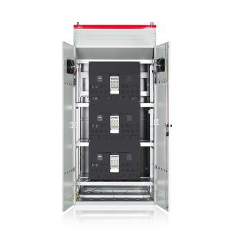
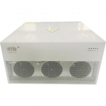
5.3.2 Power cabinet
Power cabinet is mainly composed of power cells which constitute the main body of FGSVG reactive power compensation device. Power cell is divided into three phase to install, and the numbers of each phase is same. The output waveform is superimposed by each cell. Each power cell has to bear the full output current, 1/N of phase voltage, 1/3N of output power. Because of the cell module will produce heat during operation, using fan on the top cabinet or cabinet door to forced cooling is necessary.Power cell arrangement is as shown in Figure 2,

Figure 2 power cabinet cell arrangement and Power cell (Module)
Deliberately selected film DC capacitors are made from the PHD high temperature resistant PP film manufactured by Treofan Germany GmbH, guarantee product reliability.
Each power unit provides complete protections (over-current, over-voltage, over-heat, drive trigger exception and communication exception). Optical fiber communication is used between the controller and power units with completely and reliably separation of low voltage from high voltage. In this way, the system excels in safety and EMI immunity.
Modular-based design makes all power units share the same structure and ensures high interchangeability. Only two or four lead-out terminals and two optical fiber connectors are designed as external interfaces, a design that ensures easier maintenance and service. Each power unit provides sine PWM control through IGBT-based inverter bridge so that the unit output waveform shown in Figure 3 can be obtained.

Figure 3 output waveform of power cell and superimposing waveform of each cell
After each power unit is chained, three phases that are star or delta connected are then connected to the grid through reactors. Superimposition of all PWM waveforms from all units result in the square PWM waveform that is similar to a sine waveform.
6 STATCOM Operation in 40MWp Floating Solar Farm on Sanlihe Reservoir,
The primary wiring diagram for State Grid’s 40MWp floating solar farm on Sanlihe Reservoir, Zhuxiang Town, Changfeng County is as follows,

Figure 4 40MW solar plant Single Line Diagram
The total installation capacity of this project is 40MWp. With 64 units of 630kw inverters connected to the grid, the AC output voltages of connected inverters are 0.3kV and 0.27 kV, which are increased to 35kv via a step-up transformer, and converged to the 35KV outlet spacing in Rayspower’s 110kv transformer substation.
To meet its operation needs, the Floating Solar Farm purchased a 9Mvar dynamic reactive power compensation device (HVSVG-C9.0T) produced by WindSun(ZDDQ partner). The device is mounted to the 35kV grid via a 10Kv/35kV step-up transformer.
HVSVG provides proper performance after put into production, meeting the Solar Farm’s requirement for reactive power compensation device, and has passed acceptance. The device has the following characteristics:
(1) Appropriate design for easy installation. Module-based structure simplifies installation and maintenance, reduces on-site wirings and reduces commissioning workload such that it is quickly put into production.
(2) Easy operation and observation
HVSVG has a simply structured control panel which is easily operated and provides standard communication with witch, the communication with its host is available. On the panel, all states can be displayed and function setting can be readily made.
(3) Stable power factor that can be preset
Connection of the Solar Farm to grid requires a power factor that is between 0.95 and 0.99 when STATCOM is in use, and a power factor that is about 1 when STATCOM is not in use. To maintain electricity system’s stability, STATCOM supply inductive reactive power to meet the power factor requirement. With STATCOM in use, power factor of the 40MWp Floating Solar Farm has been kept at 0.98~0.99, which meets both power generation demand and power factor requirement.
(4) Improved grid electricity quality
A Statcom is able to filter harmonics. Harmonic current at the grid connection point after STATCOM was put into production has been kept below 2%. Compared with conventional reactive power compensation devices, STATCOM provides much higher response within 5 ms. It can suppress grid voltage dip and flicker. The waveform after grid connection is given in Figure 5.
(5) Reduced energy consumption
HVSVG’s operating efficiency is up to 99.97%, lowering the electricity consumed by the Solar Farm itself.

Figure 5 power factor powerformance after statcom connection
7 Conclusion
The 40MWp Floating Solar Farm’s operation over the last one and a half years indicates that HVSVG provides a stable and reliable performance in a highly automated way, improves grid quality and meets the expectation. STATCOM is an efficient and quality reactive power compensation technique developed in recent years, a new application of electricity, electronics and inverter technologies to new energy. It plays an important role in controlling harmonics, reactive power compensation and keeping grid stability for PV stations.
ZDDQ Related Products


NO.25,JINHE RD,HUAIYUAN ECONOMIC DEVELOPMENT ZONE ,BENGBU,ANHUI
Scan to WhatsApp: