Variable Frequency Drives (VFDs) have become essential in modern industrial systems. They provide accurate motor speed control, reduce mechanical stress, and can significantly improve energy efficiency. However, there is another side of VFD technology that is often underestimated: harmonic distortion.
In low-voltage distribution systems, a large number of VFDs can become an important source of harmonic currents. More importantly, these harmonics may interact with transformers, cables, reactors, and power factor correction capacitors, creating a much more serious problem — harmonic resonance.
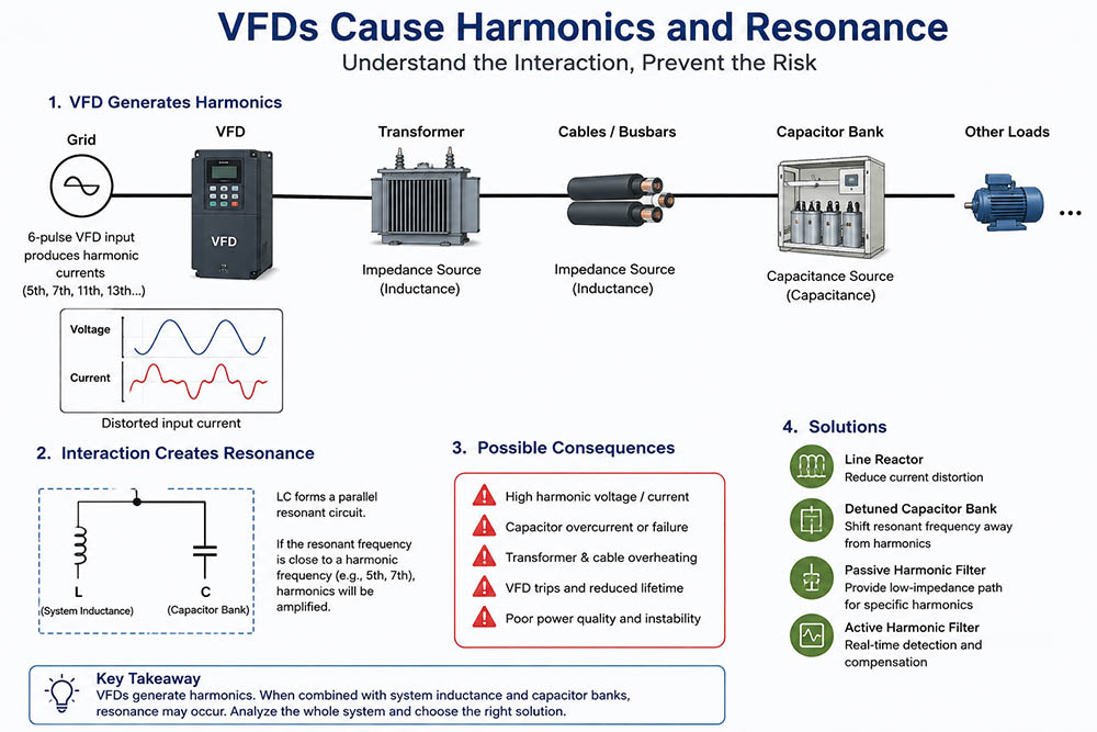
A conventional low-voltage VFD normally uses a rectifier at its input side to convert AC power into DC power. A DC-link capacitor then smooths the DC voltage before the inverter section converts it back into variable-frequency AC for the motor.
The problem is that the input rectifier does not draw a perfectly sinusoidal current from the grid.
Instead, current is concentrated around certain portions of the voltage waveform, producing a distorted input current. For a typical six-pulse VFD, the characteristic harmonic orders include the 5th, 7th, 11th, 13th, 17th and 19th harmonics.
For example, if the fundamental frequency is 50 Hz:
Therefore, even when the grid voltage looks relatively clean, a large population of VFDs can inject considerable harmonic current into the distribution network.
Harmonic current alone does not necessarily mean that the electrical system will immediately fail.
The real danger appears when the harmonic current encounters an unfavorable system impedance.
A typical industrial low-voltage system contains:
Transformer inductance + cable inductance + capacitor bank capacitance
These inductive and capacitive elements can form an LC circuit.
Every electrical system containing inductance and capacitance has natural resonant frequencies. If one of these frequencies approaches a significant harmonic generated by the VFD, the harmonic current or voltage can be strongly amplified.
This is known as harmonic resonance.
In particular, power factor correction capacitors can interact with the inductance of transformers and distribution lines to create parallel resonance. When the resonant frequency is close to a characteristic harmonic, the system can attract and amplify harmonic current.
This is why simply saying “the VFD produces harmonics” is not enough. Engineers also need to ask:
What happens to these harmonics after they enter the electrical network?
Consider a factory with the following equipment:
Under normal operating conditions, the capacitor bank improves the fundamental-frequency power factor.
However, when the VFDs generate 5th and 7th harmonic currents, the capacitor bank changes the frequency response of the entire system.
If the system's parallel resonant frequency is close to the 5th harmonic, the harmonic voltage may increase significantly. At the same time, the capacitor current can become excessive.
The consequences may include:
In severe cases, a capacitor bank that was originally installed to improve power quality can actually become part of the problem.
One common misunderstanding is that a low power factor should simply be corrected by installing more capacitors.
For systems dominated by VFD loads, this approach can be risky.
The first step should be to distinguish between displacement power factor and true power factor. A VFD may have a relatively good fundamental power factor while still producing significant harmonic current.
Therefore, increasing capacitor capacity without checking harmonic impedance can move the system's resonant frequency closer to a problematic harmonic.
In other words:
More capacitors ≠ better power quality.
The correct solution must consider both reactive power compensation and harmonic characteristics.
There is no single solution suitable for every VFD system. The appropriate method depends on the VFD capacity, harmonic spectrum, short-circuit capacity, transformer impedance, capacitor capacity and required power-quality performance.
Installing an AC line reactor at the VFD input can reduce the severity of current distortion and limit the interaction between the VFD and the upstream power system.
It is a relatively simple first-level solution for many small and medium VFD installations.
Instead of connecting ordinary capacitors directly to the system, a reactor can be connected in series with the capacitor bank.
The purpose is not simply to “filter” one harmonic, but to shift the system's resonant frequency away from major harmonic frequencies.
This approach can significantly reduce the risk of harmonic amplification while still providing reactive power compensation.
A tuned passive filter combines capacitors and reactors to create a low-impedance path for selected harmonic currents.
For typical six-pulse VFD systems, the 5th and 7th harmonics are often important targets. A properly designed passive filter can divert harmonic current away from the supply network while also providing reactive power compensation.
However, passive filters must be designed according to the actual system impedance. An incorrectly tuned filter can introduce a new resonance problem rather than solve the original one.
When loads change frequently or the harmonic spectrum is complex, an Active Harmonic Filter (AHF) can provide a more flexible solution.
Instead of relying on a fixed LC resonance point, an AHF detects harmonic components and injects compensating currents into the system.
This makes active filtering particularly attractive for facilities with multiple VFDs, variable loads and changing harmonic characteristics.
The most important lesson is that VFD harmonic problems should not be evaluated by looking at the VFD alone.
A practical power-quality assessment should consider:
VFD → Transformer → Cable → Capacitor Bank → Other Nonlinear Loads → System Impedance
The harmonic spectrum should be measured, while the system's impedance and possible resonant frequencies should also be evaluated.
For more complex industrial systems, harmonic simulation and frequency-sweep analysis can help identify whether a resonance point exists near the dominant harmonic frequencies.
This is particularly important before installing a large capacitor bank or harmonic filter.
Low-voltage VFDs bring major benefits to modern industry, but their nonlinear input characteristics can introduce significant harmonic currents into the power system.
The bigger risk is not necessarily the harmonic current itself. The real challenge occurs when VFD-generated harmonics interact with system inductance and capacitor banks, creating harmonic resonance.
Therefore, a reliable power-quality strategy should follow a simple principle:
Measure the harmonics → Understand the system impedance → Check the resonance point → Select the appropriate compensation or filtering solution.
For industrial plants with a high concentration of VFDs, harmonic mitigation should be treated as a system-level engineering task rather than simply adding capacitors or filters.
The goal is not merely to reduce THD.
The real goal is to make the entire electrical system stable, predictable and resistant to harmonic resonance.
Categories
new blog


NO.25,JINHE RD,HUAIYUAN ECONOMIC DEVELOPMENT ZONE ,BENGBU,ANHUI
Scan to WhatsApp: