Reactive Power Compensation Solution for Chemical Plants
Apr 24,2026
Reactive Power Compensation Solution for Chemical Plants
1. Problem Background and Requirements
Chemical plants typically operate numerous inductive loads, such as large motors (pumps, compressors, fans), transformers, variable frequency drives, and electric arc furnaces. During operation, these devices consume significant amounts of reactive power (Q), leading to the following issues:
-
Low power factor (Cosφ): Typically between 0.6 and 0.8, or even lower.
-
Increased line losses: Reactive current generates additional I²R losses in transmission lines, transformers, and switchgear, wasting electrical energy.
-
Increased burden on transformers and lines: Transformers and lines must transmit a larger apparent power (S), reducing their load capacity and potentially requiring premature capacity expansion.
-
Increased voltage fluctuations: Fluctuations in reactive power cause bus voltage variations, affecting the operation of sensitive equipment.
-
Penalties for power factor adjustment charges from the power supply bureau: Power supply companies generally require users to maintain a power factor of at least 0.9 (or even 0.95). Falling below this threshold incurs penalties, while exceeding it may earn incentives.
-
Core objective of the solution: By installing shunt capacitor banks to provide capacitive reactive power locally or centrally, compensate for the reactive power consumed by inductive loads, and raise the power factor to the target value (typically ≥0.95), the above-mentioned problems can be resolved, achieving energy savings, reduced consumption, voltage stabilization, penalty avoidance, and potential incentive earnings.
2. Principle of Reactive Power Compensation
-
Inductive loads (such as motors) draw lagging reactive current from the grid to establish magnetic fields.
-
Shunt capacitor banks supply leading reactive current to the grid.
-
After compensation, most (or all) of the lagging reactive current required by the loads is supplied locally by the capacitors, eliminating (or reducing) the need for long-distance transmission from the grid.
-
The grid then primarily supplies active current (P), making the apparent power (S) approach the active power (P), and significantly raising the power factor (Cosφ = P/S).
3. Compensation Method Selection (Recommended Combined Scheme Based on Chemical Plant Characteristics)
Chemical plant loads are typically characterized by large capacity, some loads operating continuously, some loads varying, and the possible presence of harmonics. A hybrid compensation scheme is recommended:
Local compensation (equipment-level compensation):
-
Applicable targets: Large, long-term, continuously operating fixed-speed motors (e.g., main process pumps, large compressors).
-
Advantages: Provides the best compensation effect, maximally reduces reactive current and losses in upstream lines and transformers, and stabilizes motor terminal voltage.
-
Disadvantages: Relatively high investment, dispersed maintenance points, need to consider the impact of motor starting and stopping on capacitors.
-
Recommendation: Implement local compensation for critical, high-power (e.g., >200 kW) continuously operating motors.
Group (workshop-level) compensation:
-
Applicable targets: A relatively concentrated group of small to medium-sized loads (e.g., multiple pumps and fans within a workshop).
-
Advantages: Lower investment compared to local compensation, more centralized maintenance, effectively reduces the reactive power burden on workshop distribution lines and transformers.
-
Disadvantages: Compensation accuracy is slightly lower than local compensation; line losses within the workshop cannot be completely eliminated.
-
Recommendation: Implement group compensation for small to medium-sized motor groups or areas with similar load characteristics.
Centralized compensation (at the main substation or distribution room):
-
Applicable targets: The total reactive power demand of the entire plant, especially the fluctuating portion of the reactive load.
-
Advantages: Relatively low investment (especially for total compensation capacity), convenient centralized installation and maintenance, easy implementation of automatic switching.
-
Disadvantages: Cannot reduce the reactive current and losses in the plant's internal branch lines, limited local voltage improvement effect.
-
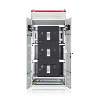
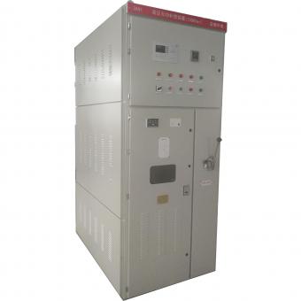
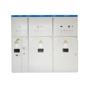
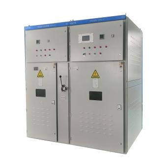
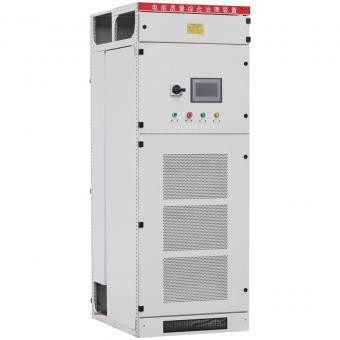
Recommendation: Essential scheme. Install automatic reactive power compensation devices in the main step-down substation or primary distribution rooms to compensate for the reactive power losses of the transformers themselves, loads without local/group compensation, and the fluctuating portion of the plant's total reactive load. This is key to meeting the power supply bureau's assessment requirements and avoiding penalties.
4. Implementation Key Points
-
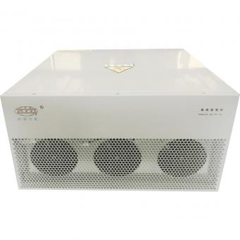
Equipment Selection: Choose reliable, standard-compliant capacitors, reactors, switching devices, controllers, and protection devices. Pay special attention to voltage rating (e.g., select 450V capacitors for a 400V system), capacity matching, and reactor rate selection.
-
Overcompensation Prevention: The controller should have overcompensation detection and interlocking logic, especially to avoid feeding reactive power back into the grid under light load conditions.
-
Protection Configuration: Comprehensive protection against short circuits, overcurrent, overvoltage, undervoltage, imbalance, temperature, and harmonic limit exceedance.
-
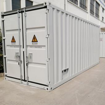
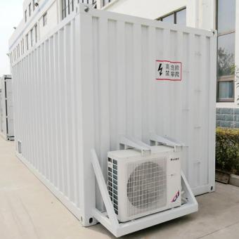
Installation Location: Follow relevant electrical codes, ensure adequate ventilation and heat dissipation, and facilitate convenient operation and maintenance.
-
Commissioning and Acceptance: Strictly commission according to specifications, verify compensation effectiveness, switching logic, and protection functions. Conduct power quality comparison tests before and after compensation.
-
Operation and Maintenance: Conduct regular inspections, record operational data (power factor, voltage, current, temperature, etc.), and perform periodic capacitor capacity testing and insulation checks.
-
By implementing this comprehensive reactive power compensation scheme, the chemical plant workshop can effectively resolve the numerous problems caused by low power factor, achieve safe, reliable, and economical operation, and realize significant economic benefits (electricity cost savings, penalty avoidance, deferred investment).
Zddqelectric Related power quality solutions: