With the advancement of industrial automation technology, variable frequency drives (VFDs) are becoming increasingly widespread, garnering growing acclaim for their excellent speed-regulation capabilities and significant energy-saving effects. However, the harmonics generated during their operation pose an increasingly serious threat to the power grid; consequently, the need to suppress harmonic interference and improve power quality has become increasingly urgent.
1. Operating Principle of the Variable Frequency Drive (VFD)
A variable frequency drive is a device that converts AC power with fixed voltage and frequency into AC power with variable voltage and frequency. Its main circuit typically employs an AC-DC-AC topology: a three-phase bridge rectifier circuit converts the standard 380V/50Hz AC mains supply into DC voltage, which is then inverted into variable-frequency AC voltage using capacitor filtering and high-power switching components (such as IGBTs or GTOs). Harmonic injection into the power grid causes additional temperature rise and insulation degradation in inductive equipment—such as motors, transformers, and conductors—thereby shortening equipment lifespan and increasing losses. It also leads to capacitor failure and damage, increases the risk of system resonance, and triggers a range of other issues, including the malfunction of protective relays and automatic devices, inaccuracies in instrumentation and energy metering, and interference with communication systems.
2. Harmonics in Variable Frequency Drives (VFDs)
Based on the operating principles of a VFD, the switching characteristics of its inverter circuit make it a typical non-linear load on the power supply circuit. When current flows through the load, it does not maintain a linear relationship with the applied voltage; this results in a non-sinusoidal current, thereby generating harmonics. Consequently, the voltage and current on both the input and output sides of the VFD contain significant high-order harmonic components.
-
Harmonics on the Grid Side of the VFD
The harmonics injected into the power grid by a VFD are primarily current harmonics. Since the VFD employs a three-phase rectifier circuit, the generated harmonics typically include orders of 6n ± 1 (where n = 1, 2, 3, ...). The 5th and 7th order harmonic currents are particularly significant; typically, the 5th harmonic accounts for 40–65% of the fundamental current, and the 7th harmonic accounts for 14–41%, while the content of other harmonic orders generally remains below 10%. However, non-characteristic harmonics of other orders may also be generated due to factors such as DC current ripple, phase imbalances in AC voltage, discrepancies in firing delay angles, and variations in commutation reactance across phases.
-
Waveforms at the VFD Output
Harmonics are present in both the output voltage and current within the inverter output circuit. For PWM-controlled variable frequency drives (VFDs)—specifically voltage-source inverters—the output voltage waveform is rectangular, regardless of the specific PWM control method employed; the harmonic frequencies are determined by the drive's modulation frequency. The current waveform is an approximately sinusoidal wave with spikes (or "fuzziness"), as shown in the figure. Clearly, such distortion in the VFD's output waveform can cause significant damage to the motor.
3. Hazards of High-Order Harmonics
-
Transformers: Harmonic currents and voltages increase copper and iron losses in transformers, causing temperature rises, compromising insulation integrity, and reducing capacity margins. Harmonics can also induce resonance and generate noise.
-
Induction Motors: Harmonics similarly increase copper and iron losses in motors, leading to temperature rises. Furthermore, harmonic currents alter electromagnetic torque and generate oscillating torque components; this causes periodic fluctuations in motor speed, impairs output efficiency, and produces noise. Additional issues include extra heat generation and temperature rise; increased repetitive peak voltages that damage insulation and shorten motor lifespan; torque pulsation; and heightened noise levels. In practice, many unexplained motor failures are attributable to harmonics. Installing a sine wave filter at the variable frequency drive (VFD) output can correct the waveform into a pure sine wave.
-
Switchgear: Harmonic currents can cause high rates of current change during startup, increasing peak transient recovery voltages. This can damage insulation and trigger unwanted tripping or malfunctions.
-
Protective Devices:Harmonics in the current flowing through protective devices can generate extra torque, alter operating characteristics, cause malfunctions, or even burn out coils.
-
Metering Instruments:Harmonics can induce extra torque in the induction discs of metering instruments, leading to measurement errors, reduced accuracy, and potential coil burnout.
-
Power Electronic Equipment:Power electronic equipment typically relies on precise zero-crossing detection or specific voltage waveform shapes for control and operation. The presence of harmonic components shifts zero-crossing points and distorts waveforms, leading to malfunctions. Computers and other electronic devices generally require a Total Harmonic Distortion (THD) of less than 5% and individual harmonic distortion levels below 3%. Higher distortion levels can cause control equipment to malfunction, resulting in production or operational interruptions and significant economic losses.
-
Power Cables: High-frequency harmonic currents induce the skin effect in conductors, generating additional heat and increasing copper losses. In particular, zero-sequence third-harmonic currents superimpose within the neutral conductor, resulting in high neutral currents—sometimes even exceeding the phase currents. This causes the neutral conductor to overheat, accelerates the aging of insulation, and can even lead to fires. Furthermore, significant harmonic currents in the neutral conductor create a substantial voltage drop across the conductor's impedance, interfering with the normal operation of various microelectronic systems.
-
Power Capacitor:As the frequency of higher-order harmonics increases, the impedance of capacitors to these harmonics decreases; this can lead to overheating—or even damage—due to overcurrent. Additionally, parallel or series circuits formed by capacitors and inductive loads within the system may experience harmonic resonance, which amplifies harmonic currents or voltages and exacerbates the associated hazards. In parallel resonant circuits formed by capacitor banks and grid inductance, harmonic levels can be amplified by a factor of 10 to 15.
4. Solution: Active Harmonic Filter Mitigation
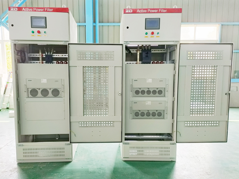
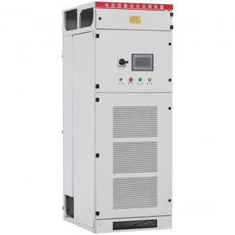
Active harmonic filter essentially acts as a harmonic source connected in parallel or series with the main circuit. It employs a high-speed DSP chip to monitor system parameters in real time and isolate fundamental and harmonic components; a compensation unit then generates a compensation current equal in magnitude but opposite in direction to the harmonic current, thereby achieving real-time harmonic compensation. Compared to passive filters, active filters offer high controllability and rapid response, are unaffected by system impedance, pose no risk of resonance, and can automatically track and compensate for fluctuating harmonics. However, they have drawbacks such as high cost and difficulties in manufacturing high-capacity units.