active power filter
  • STATCOM Applications

    STATCOM Applications

    Electrical utilities and heavy industries face a number of challenges related to reactive power. Electrical utilities may be confronted with voltage sags, poor power factor and even voltage instability. Heavy industrial applications can cause disturbances like voltage unbalance, distortion or flicker on the electrical grid. Reactive power control can resolve these issues by improving the power factor or compensating for the voltage instability. In many cases, the traditional solutions of switching capacitors is too coarse and slow to stabilize a weak network. The most advanced solution to compensate reactive power is to incorporate a Voltage Source Converter (VSC) as a variable source of reactive power. These systems offer advantages compared to standard reactive power compensation solutions in demanding applications, such as wind farms and arc furnaces, where normal reactive power control generated by generators or capacitor banks alone are too slow for the sudden load changes. Typical STATCOM applications: –– Utilities with weak grids or fluctuating reactive loads –– Unbalanced loads –– Arc furnaces –– Wind farms –– Wood chippers –– Welding operations –– Car crushers & shredders –– Industrial mills –– Mining shovels, hoists and mills –– Harbor cranes
    view more
  • What is a STATCOM?

    What is a STATCOM?

    STATCOM (or Static Synchronous Compensator) is a voltage regulating device. It is based on a power electronics voltage-source converter and can act as either a source or sink of reactive AC power. It is a member of the Flexible AC transmission system (FACTS) family which detects and instantly compensates for voltage fluctuations or flicker, as well as controls power factor. As a fully controllable power electronic device, the STATCOM is capable of providing both capacitive and inductive VARs.
    view more
  • Dynamic Power Quality Technology for modern infrastructure

    Dynamic Power Quality Technology for modern infrastructure

    A changing electrical network brings new power quality issues. Today the way we generate, use, and control our energy is changing. New and renewable generation and distribution technology is becoming common, and combined with more dynamic and complex load profiles, there are more challenges faced by the network and energy users to provide high power quality. A new way to improve your power quality. A modern and changing transmission and distribution network requires new solutions to correct power quality issues. ZDDQ brings to market a new range of dynamic power quality solutions designed to provide high power quality to your installation. Dynamic Power Quality Solutions The energy market of today is radically different and continually changing. New generation and distribution technologies, such as solar and wind, are changing the infrastructure of the electrical network, and new loads and technology are changing the way power is drawn and used. Today’s load profiles are becoming more dynamic and fast changing, leading to more demanding power requirements and rapid reactive power needs. As well as this, the technology powering these loads are utilising solid state technology more often–these ‘non-linear’ loads draw current non-sinusoidally, creating harmonic disturbances on the network. Modern problems such as these require modern solutions. ZDDQ Electronics range of Power Quality units use high quality inverter technology to provide market leading solutions to poor power quality problems. Power Quality High Power Quality is the ability to deliver a clean and stable power supply. Essentially this is a pure, noise free, sinusoidal wave, with voltage and current in phase. There are three common power quality issues faced across the electrical network today: Power Factor: a poor power factor results in a phase angle difference between the current and voltage waveforms in an AC system. Harmonics: multiples of the fundamental frequency impacting the supply, resulting in heavily distorted waveforms. Network 3 phase unbalance: differing line voltages across phases, caused by unbalanced loads and single phase and phase-to-phase connections. Poor power quality has many negative impacts on an installation, from nuisance tripping and losses through to shut down and equipment damage. These impacts often have a direct effect on the bottom line and your facility. Improving power quality can reduce your energy costs, increase efficiency, and improve service life of infrastructure. Superior Technology Better, reliable, adaptable, affordable and modern technology to improve power factor and mitigate harmonics. Static Var Generator The Static Var Generator (SVG) is the newest technology on the market used to correct power factor issues. Utilizing solid state inverter technology, the SVG delivers instantaneous power factor correction to the grid by injecting current within 20ms. With no risk of over- or under-correction, the SVG can correct the power...
    view more
  • Active Filters

    Active Filters

    Active Harmonic filters are systems employing power electronics. They are installed either in series or in parallel with the nonlinear load to provide the harmonic currents required by nonlinear load and thereby avoid distortion on the power system. The active filters inject, in opposite direction, the harmonics drawn by the load, such that the line current Is remains sinusoidal. They are effective and recommended for the commercial installations comprising a set of devices generating harmonics with a total power rating less than 200 kVA (variable – speed drives, uninterruptible power supplies [UPSs], office equipment, etc.). Also, they are used for the situations where the current distortion must be reduced to avoid overloads. Where: Is = source current; Iact = current injected by active filter; Ihar = harmonic current generated by nonlinear load. In general, active harmonic filters(AHF) are special harmonic filters. Active filter is usually utilized in the form of a parallel filter. Note that this part does not analyse the differences between parallel filters and serial filters. Sometimes, for the term ‘active filter’, the term ‘active harmonic filter’ is more common. In contrast to the passive filter described above, this filter improves everything right down to the sinusoidal shape of currents or voltages at the connection point. Active filters supply harmonic currents used by the consumer so that, under ideal conditions, only the fundamental frequency current is still obtained from the distribution network of the local distribution system operator (power utility). Most active filters are digital (i.e. the harmonic spectrum is determined by amount and phase location from the current measurement and an appropriate counter-phase current spectrum is generated). Most of the ‘active harmonic filters’ on the market today are current controlled and can filter the harmonic current of a measured load. The harmonic level from the MV or the harmonic generators outside the measuring circuit are not affected by this. AHF can filter harmonic currents up to their nominal current, whereby an individual so-called derating factor (reduction factor) must be considered for every specific frequency. Examples of typical applications of the active filter are: 1.Distribution networks in office buildings with a lot of nonlinear loads which cause a total harmonic distortion of THD-I · S/Sr > 20%. 2.Distribution networks whose voltage distortion caused by harmonic currents must be reduced to avoid malfunctions of sensitive loads. 3.Distribution networks whose harmonic current must be reduced to avoid overloads; in particular, those of the neutral conductor. Some additional typical applications are as follows: 1.Power inverter load with high harmonic feedback and low reactive power requirements. 2.Networks with a high share of the third harmonic due to the use of single-phase consumers. Some important characteristics of active filters are as follows: 1.Most active fi...
    view more
  • Active Harmonic Filter

    Active Harmonic Filter

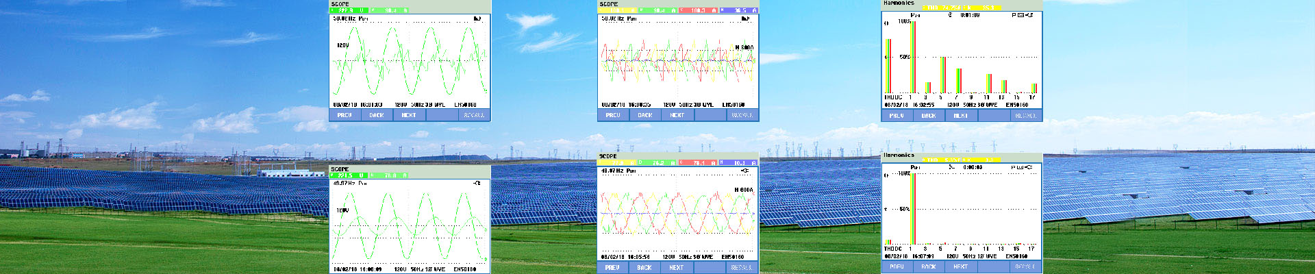
    Overview of Active Harmoinc Filter Active Harmonic Filter(AHF) is a perfect comprehensive solution to power quality problems such as harmonic wave, reactive power, and 3 phase load unbalance. AHF is connected in parallel in power grid, to detect the harmonic wave in real time, generate the reverse-phase compensation current through the converter, and dynamically filter the harmonic wave. The operation of AHF is unaffected by power grid structure and load type, and it will not produce harmonic oscillation with the system, thus perfectly realizing harmonic wave control of various loads. AHF can also realize dynamic reactive compensation, and control the capacitor switching, to improve the power factor. Meanwhile, Active Harmonic Filter has the function of controlling the 3 phase load current unbalance, thus comprehensively solving various power quality problems with power grid. Principle of Active Harmoinc Filter Key Features of Active Harmonic Filter Multifunctional: Harmonic, reactive power and imbalance compensation High harmonic filtering rate: Up to 98% Excellent reactive compensation: High speed, Precise (-0.99≤PF≤0.99), Step-less, Bi-directional (capacitive and inductance) compensation Excellent imbalance correction: Both negative and zero sequence, mitigates neutral current Wide input voltage & frequency range, adapts to tough electrical environments Low thermal loss (≤3% of rated AHF kVA), efficiency ≥ 97% High stability: Infinite impedance to grid, avoids harmonic resonance problems Flexible application: Modular design, embedded in standard or customized cabinet Easy installation and maintenance: Plug-in installation for AHF module replacement and expansion Wide capacity range: 30A~600A for a single cabinet, up 10 cabinets in parallel Environmental adaptability: -10~50°C temperature, compatible with diesel generator Complete protection: Grid Over/Under voltage, AHF over current, over temperature, and more. All faults are recorded in the event log, which is convenient for failure analysis Typical Application of Active Harmonic Filter Harmonics occur usually as follows, ◆Overheating of transformers and conductors ◆Generator instability ◆Capacitor failure ◆Nuisance tripping of fuses and circuit breakers ◆Damage to or failure of sensitive electronic equipment including drive failure ◆Telephone interference ◆Motors experiencing overheating, audible noise and reduced service life ◆High energy costs ◆Downtime and loss of production due to equipment instability. AHF Modular Datasheet Number of phases (system input) 3-phase 3-wire or 3-phase 4-wire Rated frequency 50/60Hz Rated voltage 400 V ±20% Response time <5ms Harmonic mitigation performance 2nd to 50th harmonic Filter Efficiency >97% Total harmonic current distortion THDi <5% Reactive power compensation Rate >0.98(inductive and capacitive compensation) 3 phase unbalance compensation effect <5% Active Loss of system <3% Inverter topology IGBT Controller DSP+FPGA Current ...
    view more
  • Sizing Active Harmonic Filter from Power Analyser Data

    Sizing Active Harmonic Filter from Power Analyser Data

    The Graph below shows Harmonic Current Distortion in the form of %THDi. This is hovering between 20 and 25%. Ideally, it should be less than 10% and preferably less than 8% THDi. The highest value of average total harmonic distortion (%THDi) across three phases was calculated from raw data. This value is 24.19%THDi and was recorded at time shown. At the same time, average line current (Amps) across three phases was 516.83A. Analysis of Findings From data above, Highest Average %THDi = 24.19% At the same time, Average I RMS across three phases was 516.83A. Taking X to be = fundamental frequency current I RMS = √(12 + 0.24192) * x = 516.83A 1.02884 * x = 516.83 x = 516.83 / 1.02884 = 502.34A Calculate harmonic current I RMS = √(502.342 + Harmonic Current2) = 516.83A 502.342 + Harmonic Current2 = 267113 Harmonic Current2 = 267113 – 252345 = 14767.8A Thus Harmonic current = 121.52A If %THDi = 8% (An appropriate value to satisfy electrical supply utilities) I RMS = √(502.342 + (0.08*502.34)2) = √(252345 + 1615) =503.94A I RMS = √(502.342 + Harmonic Current2) = 503.94A 502.342 + Harmonic Current2 = 253955.5 Harmonic Current2 = 253955.5 – 252345.5 = 1610A Thus Harmonic current = 40.125A Thus– To reduce % THDi at Incomer from 24.91% to 8% requires 81.4A of harmonic filtering (121.52-40.125). Active Harmonic filters come in sizes of 60A, 120A, 200A and 300A. To reduce %THDi to a level of 8% would require a 120A filter. Check performance when filter installed.
    view more
  • Static VAR Generator SVG

    Static VAR Generator SVG

    Overview of Static Var Generator Static Var Generator (SVG) also known as instantaneous stepless reactive power compensators are the ultimate answer to power quality problems caused by low power factor and reactive power demand for a wide  range of segments and applications. They are a high performance, compact, flexible, modular and cost-effective type of active power filters (APF) that provide an instantaneous and effective  response to power quality problems in low or high voltage electric power systems. They enable longer equipment lifetime, higher process reliability, improved power system capacity and stability, and reduced energy losses, complying with most demanding power quality standards and grid codes. Low power factor increases the active energy losses of installations and affects their stability. It is typically caused by inductive or capacitive loads that demand extra reactive power to perform properly. Other contributors to low power factor are harmonic currents produced by nonlinear loads and the change of load in the electric power system. SVG deliver real-time inductive or capacitive reactive power compensation. Rapid response time provides stable and accurate power factor correction without the drawbacks of conventional solutions like capacitor banks and reactor banks. Principle of SVG Static Var Generator is a power electronics-based device connected in parallel with the load that requires harmonics mitigation. SVG works as a controlled current source providing any kind of current waveform in real time. When the load generates inductive or capacitive current, it makes load current lagging or leading the voltage. An SVG detects the pase angle difference and injects in real time leading or lagging current into the electric power systems, making the phase angle of the current almost the same as that of the voltage, bringing fundamental power factor to unity. Key features of SVG ◆PRECISE COMPENSATION Continuously outputs and compensates reactive power to maintain power factor >0.99. The compensation performance is 1.2 times better than a traditional compensation device (capacitor). ◆CAPABLE OF INDUCTIVE AND CAPACITE COMPENSATION Realize inductive and capacitive compensation, avoid under and over compensation issues. ◆SUPPRESS HARMONICS Configures the required amount of reactive current in real-time and compensates the reactive power to filter high order harmonics. ◆FAST RESPONSE Fast configuration capability provides fast analysis and response time. Provides cycle response <5ms and dynamic response <200us. ◆LOW VOLTAGE BENEFITS Output current is not affected by the mains voltage fluctuation, providing stable support for mains voltage. ◆MINIMAL LOSS, BETTER ENERGYEFFICIENCY Adopts new standard IGBT with low power consumption rate and improves full set device efficiency up to 97%. The system provides low power consumption. ◆MODULAR DESIGN, EASY EXTENSION No need for additional re...
    view more
  • How to improve the power factor

    How to improve the power factor

    Improving The power factor of an electrical installation consist of giving it the means to produce a varying proportion of the reactive energy that it consumes itself. Different systems are available to produce reactive energy, particularly phase advancers and shunt capacitors (or serial capacitors for major transport networks). The capacitor is most frequently used given: • It’s non‐consumption of active energy, • It’s purchasing cost, • It’s easy use, • It’s service life (approximately 10 year), • It’s very low maintenance (static device) The capacitor is a receiver composed of two conducting part (electrodes) separated by an insulator. When this receiver is subjected to a sinusoidal voltage, it shifts its current, and therefore it’s (capacitive reactive) power, by 90° forward the voltage. Conversely, all other receivers (motor, transformer, etc.) shift heir reactive component (inductive reactive power or current) 90° backward the voltage. The composition of these (inductive or capacitive) reactive powers or current gives a resulting reactive power or current below the existing value before the installation of Capacitors. In simpler terms, it can be said that inductive receivers (motors, transformers, etc.) cons energy, while capacitors (capacitive receivers) produce reactive energy.
    view more
  • Capacitor banks

    Capacitor banks

    What is Capacitor banks? Capacitor banks, a group of several capacitors of the same rating that are connected in series or parallel with each others, help to improve the quality of the electrical power and gives us the more efficient operation of the power system. Capacitor banks are inexpensive if we compare the benefits they deliver to overall power system and can be easily installed anywhere on the network. Automatic Power-factor Correction (APFC) Capacitor Banks also known as Shunt Capacitor Banks (SCB) are installed to provide reactive compensation and power factor correction. The use of APFC improve voltage regulation, saves power loss and improve transmission capabilities. What Does a Capacitor Bank Work? Capacitor banks, work on the same theory that a single capacitor does; they are designed to store electrical energy, just at a greater capacity than a single device. An individual capacitor consists of two conductors which are separated by a dielectric or insulating material. When current is sent through the conductors, an electric field that is static in nature then develops in the dielectric which acts as stored energy. The dielectric is designed to permit a predetermined amount of leakage which will gradually dissipate the energy stored in the device which is one of the larger differences between capacitors and batteries. Typical Applications Our modern world of electronics requires a lot of energy. To meet this demand, energy must be stored electrically for easy access. Capacitors are ideal for storing large electrical energy charges as well as conditioning the flow of energy as needed. Here are some of the typical uses for capacitor banks: • Shunt Capacitor: A shunt is a mechanism that allows electric current to pass around another point in the circuit by creating a low-resistance path. In electrical noise bypass applications, capacitors are used to redirect high-frequency noise to ground before it can propagate throughout the system, but especially to the load. Shunt capacitor banks are used to improve the quality of the electrical supply and thus improve the efficiency of the power systems. • Power-Factor Correction: In transformers and electric motors, capacitor banks are used to correct power-factor lag or phase shift in AC Power Supplies.The power factor of an AC power system is a comparison of the power used by the load, called the “real power,” divided by the power supplied to the load, known as “apparent power.” In other words, the power factor is the ratio of the useful work performed by a circuit compared to the maximum useful work that could have been performed at the supplied voltage and amperage. In electric power distribution, capacitor banks are used for power-factor correction. These banks are needed to counteract inductive loading from devices like electric motors and transmission lines, thus making the load appear to be mostly resistive. In essence, power-factor correction capacitors increase the current-carryi...
    view more
  • Active Harmoni filter Applications

    Active Harmoni filter Applications

    Many industrial facilities place poor power quality at the top of the list of inefficiency factors responsible for losses due to reduced productivity and lower quality of products. Optimal electrical power utilization becomes a challenge, as well as a necessity to keep up with everincreasing energy demand without drastic increases in energy costs. Large industrial, commercial and institutional power users can benefit from centralized medium voltage reactive power compensation systems. Medium voltage solutions typically require lower initial capital expenditures ($/kVAR) than low voltage solutions while addressing most common power quality problems. Medium voltage metal-enclosed compensation systems provide centralized solution approach with attractive installation options supporting the scale and scope of large electrical services. Typical installations can be found at automotive, pulp/paper, steel, petrochemical, mining/mineral and other large industrial facilities. Many large commercial and institutional customers with medium voltage distribution network can also take advantage of medium voltage reactive compensation systems. Low voltage capacitor compensation systems can provide similar benefit of centralized solution at attractive costs for most mid and small industrial, commercial and institutional users. It offers very flexible, yet effective power factor compensation system in the low voltage network. An AHF can be used alone or in conjunction with other power quality correction equipment such as tuned harmonic filters, capacitor banks, etc. It can be placed in various locations within the electrical distribution network. Multiple units can be connected in parallel to provide higher compensation current to meet the TDD levels defined in IEEE519-1992 standard or levels defined in the plant operating requirements (5%-8%).
    view more
  • MV/HV Statcom

    MV/HV Statcom

    High Voltage SVG/STATCOM High voltage SVG/STATCOM series static var generator using IGBT as the core power modules which can quicklyand continuously provide capacitive or inductive reactive power, achieve constant reactive power, constant voltage and constant power factor control through the assessment point, and ensure the power grid is running stable, high efficiency and high quality. In the power distribution network, the small capacity STATCOM can significantly improve the power quality (improve the power factor, overcome phase imbalance, eliminate voltage flicker and fluctuation, restraining harmonic), if it is installed in some special loads (such as electric arc furnace). Main Function ZDDQ STATCOM has superior advantages compare with conventional fixed capacitor compensator, MCR and TCR. ■ Fast reactive power adjustment ZDDQ STATCOM provides continuous dynamic compensation to power factor along the load variation. It completely eradicates capacitive reactive power delivery to networks and maintain power factor in designed value for network. Statcom has advantages: 1.Fast response, able to implement dynamic compensation(both inductive and capacitive vars) in real time. 2.Effectively avoid parallel resonance. 3.Able to produce and absorb reactive power. 4.Deliver less harmonic to system. ■Restrain voltage fluctuation and flicker Power grid voltage has fluctuation and flicker when high power impact load is operating. Voltage fluctuation and flicker bring negative influence to other nearby customers’ electricity usage and sensitive load by decreasing safety for electricity usage and decreasing efficiency for production, increasing risk of faulty production. STATCOM response time is less than 1ms and it provides smooth dynamic compensation for reactive power. It is more efficient to restrain voltage flicker and reduce voltage fluctuation, improve voltage to meet standard. ■ Constant current, effectively restrain voltage drop ZDDQ STATCOM has characteristic of constant current. It has advantage in voltage control due to its reactive current output is not affected by busbar voltage. System needs more dynamic reactive power when system voltage gets lower. STATCOM reactive current output is not related to system voltage, but the conventional capacitor VAR compensator’s reactive power output is proportional to square value of voltage. STATCOM can provide better support for improving low voltage ride through (LVRT) characteristic in wind power. ■Compensate negative sequence, implement balanced power supply ZDDQ STATCOM has unique chained structure to allow split-phase adjustment and realizes energy interchange between different phases. It provides balanced compensation to load negative sequence by applying Steinmetz balanced principle. STATCOM makes current flow into system with balanced power and desired reactive power. ■Resistance to harmonics, able to compensate the part of harmonic current Due to widely applications of nonlinear load, harmonics ...
    view more
  • Reactive Power and Voltage Control of a Transmission Line

    Reactive Power and Voltage Control of a Transmission Line

    For understanding the relationship between the Reactive Power flow in a Transmission Line and Voltage drop, we will consider Short Transmission Line for simplicity. A short transmission line is one whose length is less than 80 km. For short Transmission Line Resistance and Reactance of line is assumed lumped. The important thing for short Transmission Line is that Shunt Capacitance is neglected because as the line is short the effect of shunt capacitance will be less while the reactance will predominate. By using the above philosophy we can represent a short Transmission Line as shown in figure below. Vs = Sending End Voltage Vr = Receiving End Voltage R = Line Resistance L = Line Inductance Z = Impedance of Line Is = Sending End Current Ir = Receiving End Current Now, The sending end Voltage Vs is related to the receiving end voltage Vr as below Vr ≈ Vs – ZIr where Z is the series impedance of the line consisting of resistance R and inductive reactance X. Z=R+jX Therefore, Vs – Vr ≈ ZIr ≈ RIrcosφ+ XIrsinφ ≈ (RP+XQ)/Vr as VrIrcosφ =P and VrIrsinφ =Q Now as R is quite small in comparison with X, it can be further simplified as: Vs – Vr ≈ (XQ)/Vr This expression indicates that following important points: The voltage drop for a given Receiving End Voltage Vr depends on Reactive Power Flow,Q. In a constant voltage line with Vs and Vr constant at all loads, then (XQ)/Vr is to be a constant which is achieved by varying Q as Vr tries to vary. Thus by controlling the Reactive Power flow through the Transmission Line voltage control is achieved.
    view more
1 2 3 4 ... 11

a total of 11 pages

Send a Message
welcome to zddq
If you are interested in our products and want to know more details,please leave a message here,we will reply you as soon as we can.

Home

Products

about

contact