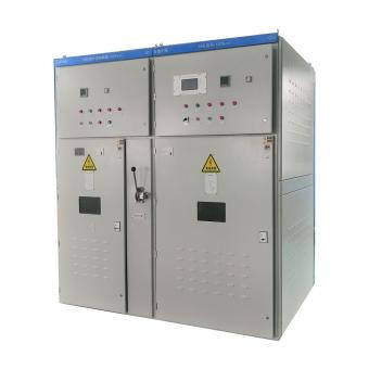
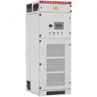
Power Factor Correction and Variable Speed Drives
Oct 25, 2019
As a general rule, standard power factor correction systems should not be used when
there are Variable Speed Drives (VSD’s) connected to the same point of connection
unless some precautions are taken.
Two situations arise when using power factor correction systems:
1. Installation of the power factor correction between the VSD and the motor, and
2. Installation of the power factor correction on the line side of the VSD
In the first case, power factor correction should not in any case be connected between
the output of the VSD and the motor. In typical DOL situations, some installations will
have a fixed KVAR value of capacitors sized to counteract the motors inductive reactance
hence increase the power factor on the supply line. Be cautious when replacing DOL
components with a VSD – if there are PF correction capacitors connected to the motor
remove them as premature damage to the inverter and motor will occur due to the high
frequency switching voltage occurring on the output of the inverter. Most capacitors are
not designed to withstand the high switching currents produced by VSD’s.
In the second case, power factor correction can be installed on the line side of the VSD
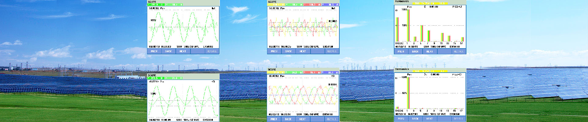
but only under certain conditions. In all cases, VSD’s produce a certain level of harmonic
distortion back into the main supply. This harmonic distortion is in the form of both
THID (total harmonic current distortion) and THVD (total harmonic voltage distortion) and
the levels of this THD is dependant upon the size of the drive, the supply transformer
impedances, short circuit levels, primary and secondary voltage levels plus cable lengths
and cable size.
Because of the inherent harmonic distortion produced by the VSD’s, the capacitors within
power factor correction equipment will cause any THD to be amplified which results
in higher voltage impulses applied to the input circuits of the inverter and the energy
behind the impulses is much greater due to the energy storage of the capacitors. This
will in turn prematurely damage the input rectifier of the VSD causing costly repairs.
In addition, the increased current and voltage transients on the line side are passed
back through the PFC capacitors causing increased operating voltage and current,
which produces higher operating temperatures and may cause premature failure of the
capacitors.
By reducing the effects of THVD and THID through the use of input reactors, harmonic
filters, active harmonic filtering on the line side of the VSD or using a 12-pulse rectifier
(or even better an Active Front End solution), this reduces the effect of the transient
impulses which can damage both the VSD and the PFC capacitors. Ensure that the
capacitors used in the PFC system have a harmonic tolerance level greater than the
harmonic distortion produced by the VSD installation.