Designing a STATCOM (Static Synchronous Compensator) for a power plant is a complex, multi-disciplinary engineering task. It's not a single-item purchase but a custom-engineered system.
Here is a comprehensive breakdown of the design process, from concept to implementation.
Before any design begins, you must clearly define the problem the STATCOM is intended to solve.
Primary Objective:
Voltage Support & Stability: The most common reason. To maintain the grid connection point (Point of Common Coupling - PCC) voltage within strict limits, especially during load changes, faults, or generator trips.
Power Factor Correction: To improve the power factor of the plant's auxiliary load or the export to the grid, avoiding utility penalties.
Transient Stability Enhancement: To provide fast reactive power support during and after faults, preventing generators from losing synchronism with the grid.
Damping Power Oscillations: To suppress low-frequency oscillations (0.2-2.0 Hz) that can occur between generators or between power plants.
System Study & Data Collection:
Load Flow Analysis: To determine the steady-state reactive power deficit/surplus at the PCC.
Short-Circuit Analysis: To size equipment for fault current withstand capability.
Transient Stability Study: To simulate the system's response to faults, generator loss, and switching events. This determines the dynamic performance requirements.
Harmonic Analysis: To understand the existing harmonic distortion and plan for filters.
Key Data Points:
System voltage (kV) and frequency (Hz).
Short-circuit level (MVA) at the connection point.
Required dynamic reactive power range (e.g., +100 MVAR to -100 MVAR).
Response time requirement (typically < 1 cycle, e.g., 20ms).
Creating the Technical Specification:
This document becomes the bible for the project. It includes:
Rated Power (MVAR): The steady-state and short-duration overload capability.
Voltage Range: The operating window (e.g., 0.9 pu to 1.1 pu).
Response Time: From a control signal to 90% of the requested output.
Losses: Maximum allowable losses at full load.
Environmental Conditions: Ambient temperature, altitude, humidity.
Grid Code Compliance: Must meet the specific requirements of the local grid operator (e.g., NERC, ENTSO-E).
This is where the technical teams design the subsystems.
Topology Selection:
Voltage Source Converter (VSC): This is the standard for modern STATCOMs.
Multilevel Topologies: To achieve high voltage and power levels with low harmonic distortion. Common choices are:
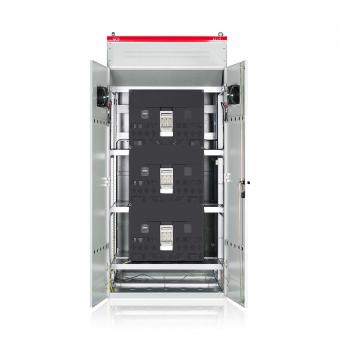
Modular Multilevel Converter (MMC): The industry standard for high-power applications (>50 MVAR). Excellent scalability and waveform quality.
Cascaded H-Bridge (CHB): Very good performance, common in medium-voltage applications.
Neutral Point Clamped (NPC) / Flying Capacitor: Used in lower power ranges.
Main Components Sizing:
Power Semiconductors (IGBTs): Selected based on voltage and current ratings, including a safety margin. Switching frequency is a key trade-off between losses and harmonic performance.
DC-Link Capacitors: Act as the energy storage element. Sized to maintain a stable DC voltage and handle ripple current.
Interfacing Transformer:
Steps up the converter voltage to the system voltage.
Provides galvanic isolation.
Its leakage reactance is a critical design parameter for power transfer.
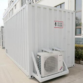
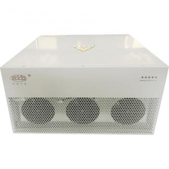
Cooling System: Forced-air cooling is common. Liquid cooling (water/glycol) is used for very high-power, dense systems to achieve better efficiency and a smaller footprint.
Protection System:
AC & DC Side Breakers: For isolation and fault interruption.
Surge Arresters: For overvoltage protection (lightning, switching surges).
Differential Protection: For internal faults in the transformer and converter.
Overcurrent/Overload Protection.
This is the most critical aspect for performance.
Hierarchical Control Structure:
Outer Control Loop (Slow, ~ms):
Voltage Control: Measures the PCC voltage and generates a reactive current reference (Iq_ref) to keep it at the setpoint.
Power Factor / Var Control: Alternative modes of operation.
Inner Control Loop (Very Fast, ~µs):
Current Control: Takes the Iq_ref (and Id_ref for active power, if needed) and generates the switching signals for the IGBTs to force the converter output current to follow the reference precisely. This loop is responsible for the fast response time.
Synchronization:
A Phase-Locked Loop (PLL) is used to precisely track the grid voltage phase and frequency in real-time. This is essential for generating correct switching signals.
Modulation Technique:
Pulse Width Modulation (PWM) for lower-level converters.
Nearest Level Modulation (NLM) for MMC topologies, which naturally produces a high-quality staircase waveform.
Harmonic Filter: While multilevel topologies produce low harmonics, a small passive filter is often included to absorb residual harmonics and prevent resonance.
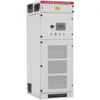
SCADA & HMI: For remote monitoring, control, and data logging.
Auxiliary Power Supply: A reliable power source for cooling, control, and protection systems.
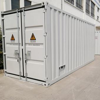
Civil Works & Layout: Design of the foundation, cable trenches, and building/container layout.
Procurement & Manufacturing: Components like IGBTs, capacitors, and transformers are sourced. The converter valves and control cabinets are assembled and tested in a factory.
Site Construction & Installation: Civil works are completed, and the equipment is installed.
Commissioning & Testing: This is a critical phase.
Functional Tests: Verify control and protection logic.
Power-Up Tests: Energize the system step-by-step.
Load/Performance Tests: Inject and absorb reactive power to verify the dynamic response, rating, and loss measurements against the specification.
Losses: A STATCOM is a "power consumer" (typically 1-2% of its MVAR rating). Losses translate directly to operating cost.
Footprint: Space in a power plant is often limited. MMC designs can be compact.
Reliability & Availability: Redundancy (e.g., N+1 submodules in an MMC) is often designed in to ensure the STATCOM is available when needed.
Interaction with the Grid: Careful study is needed to avoid adverse interactions with other power plant controls or nearby grid assets.
Cost: High-power STATCOMs are multi-million dollar investments.


NO.25,JINHE RD,HUAIYUAN ECONOMIC DEVELOPMENT ZONE ,BENGBU,ANHUI
Scan to WhatsApp: