Overview
Rapid growth of inductive electric loads on utility networks has impacted the efficient operation of AC electrical transmission and distribution grid by increasing the need for reactive power (VAr/kVAr/MVAr) that are required to be supplied with active power.
Install capacitor banks to reduce the reactive power demand from point of generation to point of use in high voltage networks. Bring voltage and current closer to being in phase in power grid.

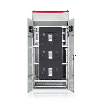
Capacitors with internal fuse(Built-in)
There are two types of fuses used for capacitors; internal and external. When the reactive power of a capacitor unit was only a few kvar, the most natural method to protect the capacitor was with an external fuse, since in the case of a breakdown the lost reactive power was small. However, now that one capacitor element has a capacity about the same value as a unit had previously it is reasonable to protect each separate element with an internal fuse.
 |
 |
|
Small capacitors banks (up to 600 kvar) are made with single phase capacitors without internal fuses, they are connected in delta and protected by means of HRC limiting current fuses. |
Capacitors banks of higher power (more than 600kvar) are made up of at least six single phase capacitors or three split-phase, without internal fuses, with capacitor bank connected in insulated double star and unbalance protection |
When using units protected by built-in fuses the number of internal series connections is determined by the bank voltage and size. The breakdown of one element and the subsequent fuse operation causes an overvoltage over the fine units.In units where all the elements are in parallel this overvoltage is very often under 0.5%.When the unit voltage is low(500V about),it is relatively easy to construct units where the fuse operation is completely reliable and breaks the current from the parallel elements and units. However, when the element voltage is among 1500~2500V, the breaking capacity of such a fuse is not adequate to break the high current at a short circuit,even with several KV recovery voltage,unless the fuse is specially constructed. In the event of a fault it is operated quickly and reliably by part of the unit enery before high energy from parallel connected units has any adverse effect.
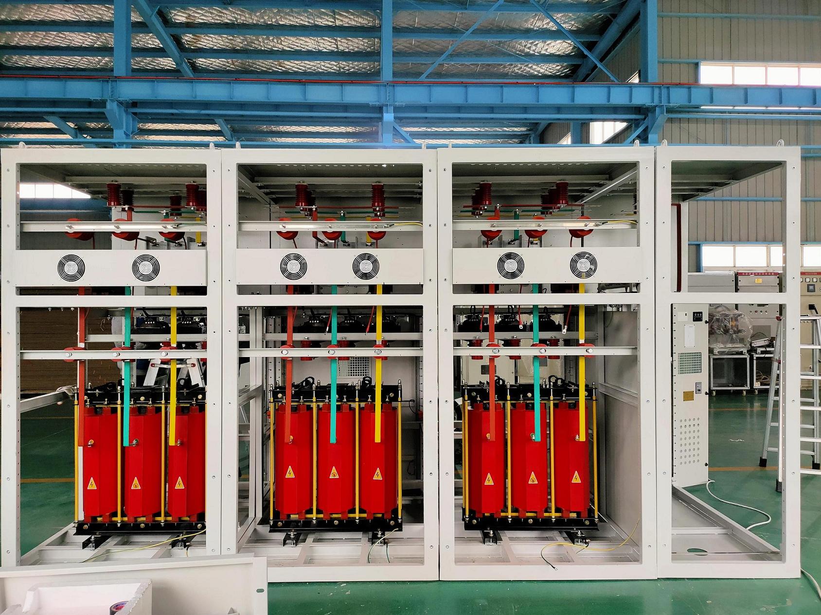
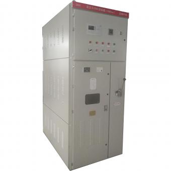
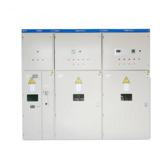
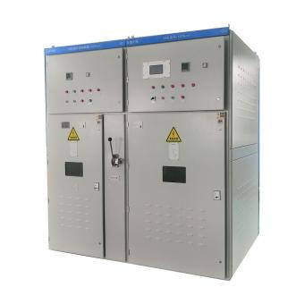
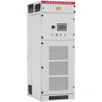
ZDDQ high voltage Capacitor banks and filters
High voltage capacitor banks are used to compensate reactive power,improve Power Factor, and provide voltage support.
By installing a capacitor bank it is possible to reduce the reactive power absorbed by the inductive loads in the system and consequently to improve power factor.
It is suitable to have cosφ a little in excess of 0.9 to avoid paying the penalties from electricity company. cosφ must not be too close to unity, to avoid the leading currents in of the electrical system.
The choice of the correct power factor correction equipment depends on the type of loads present and on their way of working.
Central or Individual compensation?
The choice is between CENTRAL COMPENSATION and INDIVIDUAL COMPENSATION.
The individual compensation is a simple technical solution: the capacitor and the user equipment follow the same sorts during the daily work, so the regulation of the cosφ becomes systematic and closely linked to the load.
It is clear that the solution of the individual compensation becomes too expensive for the high number of capacitors that have to be installed. Most of these capacitors will not be used for long period of time.
Individual compensation is more effective if the majority of the reactive power is concentrated on a few substation loads that work long period of time.
Central compensation is best suited for systems where the load fluctuates throughout the day.

Proactive approach to replacing a capacitor bank is highly recommended.
High quality capacitor banks are often the most cost-effective solution for power factor and harmonic-related technical issues and to avoid utility penalties. While the design lifetime is 20+ years, the actual and evolving operating environment and the lack of routine maintenance can accelerate aging and lead to premature failure. It is recommended that facility managers and service providers closely track capacitor bank performance, execute preventative maintenance regularly, and plan their upgrade or replacement proactively before an end-of-life failure brings disruptive and expensive consequences.


NO.25,JINHE RD,HUAIYUAN ECONOMIC DEVELOPMENT ZONE ,BENGBU,ANHUI
Scan to WhatsApp: